Thermoelectric transducing material, and method for producing the same

a technology of thermoelectromotive force and transducer, which is applied in the manufacture/treatment of thermoelectric devices, transportation and packaging, and natural mineral layered products, etc., can solve the problems of increasing thermoelectromotive force or reducing electrical resistance, and achieve high quality

Inactive Publication Date: 2006-06-27
PANASONIC CORP
View PDF6 Cites 6 Cited by
  • Summary
  • Abstract
  • Description
  • Claims
  • Application Information

AI Technical Summary

Benefits of technology

[0010]More preferably, the value of x representing a composition ratio of A is not less than 0.3 and not more than 0.7. With such a feature, the thermoelectric transducing material exhibits more improved thermoelectric transducing performance.
[0034]The electro-discharge process is preferably ion impact vapor deposition. This feature makes it possible to form a film of high quality.

Problems solved by technology

Though it is not clear why such a compositional modulation of A results in improved thermoelectric transducing performance, it can be conceived that movements of strongly correlated electrons, which are characteristic of this type of oxide material, are influenced at an interface of compositional modulation, which leads to an increase in thermoelectromotive force or a decrease in electrical resistance.

Method used


Image

  • Thermoelectric transducing material, and method for producing the same
  • Thermoelectric transducing material, and method for producing the same
  • Thermoelectric transducing material, and method for producing the same

Examples


example 1

[0061]In this example plural thermoelectric transducing materials, which were compositionally modulated based on two-layer stacked compositional modulation by double-source sputtering, were produced by changing the kind of element constituting A. These materials were compared to each other as to thermoelectric transducing performance characteristic.

[0062]A of a layered cobaltite based substance A0.5CoO2 was constituted by two kinds of elements A′ and A″ and two kinds of elements were selected, as elements A′ and A″, from the group of Na, K, Ca, Sr and Ba consisting of alkali metal elements and alkali earth group elements. A′0.5CoO2 layer and A″0.5CoO2 layer each having a thickness of 3 nm were alternately layered on the c-plane of a sapphire substrate heated to 700C to produce a thermoelectric transducing material made of a thin film having a thickness of 600 nm. This thermoelectric transducing material was c-axis oriented and was compositionally modulated in the thickness-wise dire...

example 2

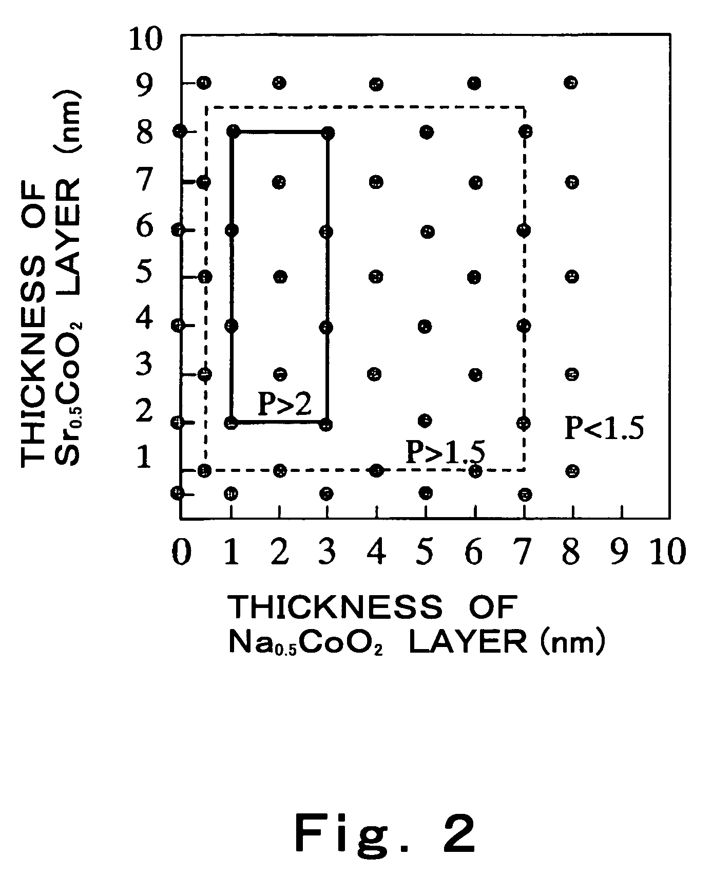
[0064]In this example, study was made of a preferable range of the thickness of each AxCoO2 layer forming a thermoelectric transducing material.

[0065]Specifically, thermoelectric transducing materials formed by a combination of Na0.5CoO2 and Sr0.5CoO2 as AxCoO2 which respectively exhibit an excellent thermoelectric transducing performance characteristic were used as samples. The correlation between the thickness of each layer and the corresponding thermoelectric trasduction power factor P was studied. These thermoelectric transducing materials, which were different in layer thickness from each other, were produced in a similar manner as in example 1.

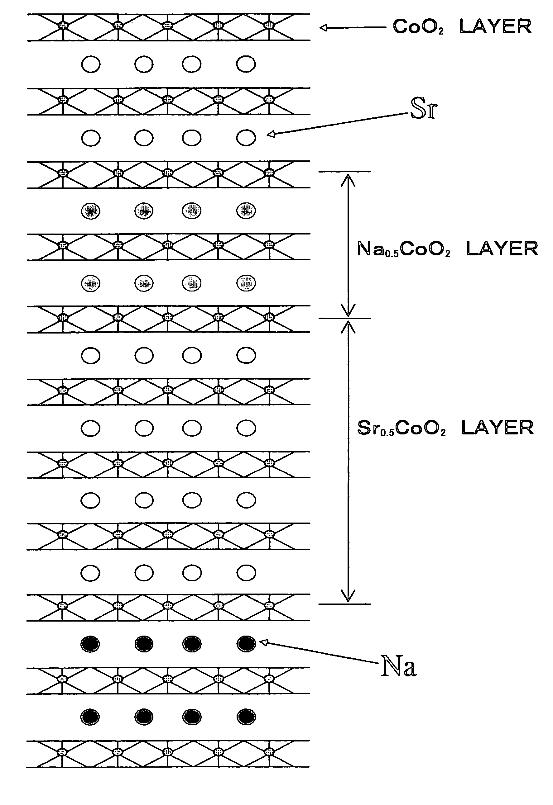
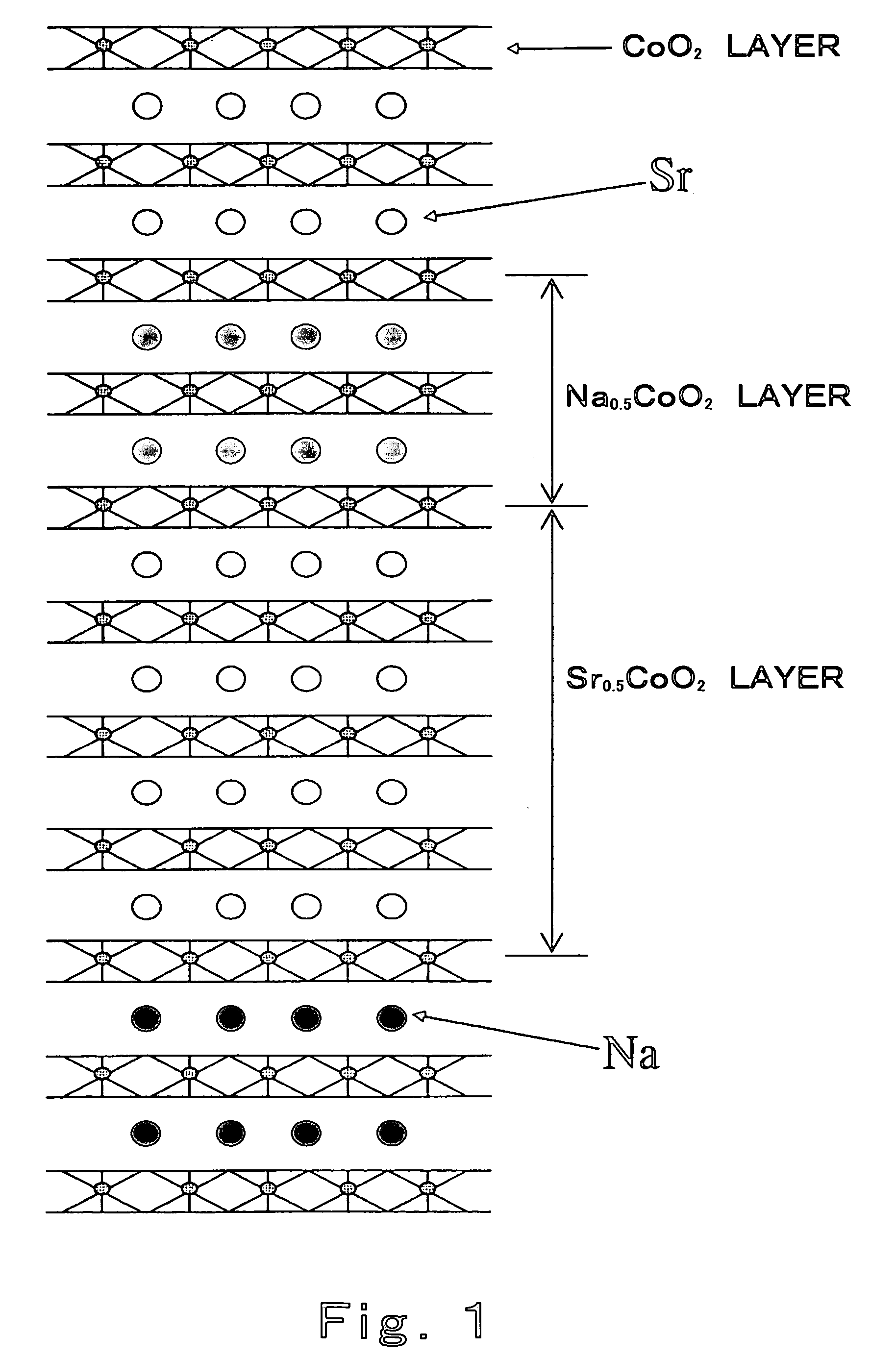
[0066]When, for example, 1 nm-thick Na0.5CoO2 layer and 2 nm-thick Sr0.5CoO2 layer are layered, a compositionally modulated structure based on two-layer stacked compositional modulation using Na and Sr is constructed as schematically illustrated in FIG. 1.

[0067]FIG. 2 is a diagram showing the correlation between the thickness of an AxCoO...


PUM

PropertyMeasurementUnit
thicknessaaaaaaaaaa
thicknessaaaaaaaaaa
thicknessaaaaaaaaaa

Abstract

A thermoelectric transducing material according to this invention includes a layered cobaltite based substance represented by the chemical formula AxCoO2, wherein A consists of an element or element group selected from alkali metal elements and alkali earth group elements and is compositionally modulated in a thickness-wise direction of layers in a structure of the layered cobaltite based substance.

Description

[0001]This is a continuation application under 35 U.S.C 111(a) of pending prior International application No. PCT / JP03 / 03787, filed on Mar. 27, 2003.BACKGROUND OF THE INVENTION[0002]1. Field of the Invention[0003]The present invention relates to a thermoelectric transducing material for forming a thermoelectric transducer adapted to perform thermoelectric cooling or thermoelectric power generation, and a method for producing the same.[0004]2. Description of the Related Art[0005]A thermoelectric transducer has a structure in which a certain number of pairs of junctions are formed by alternately joining a plurality of p-type thermoelectric transducing material and n-type thermoelectric transducing material, charge carriers of which are positive and negative, respectively, and one of each pair of junctions which forms, for example, pn junction along a current flowing direction and the other of each pair of junctions which forms, for example, np junction along the current flowing direct...

Claims


Application Information

Patent Timeline
Patent Type & Authority Patents(United States)
IPC IPC(8): B32B18/00H01L35/22H01L35/34
CPCH01L35/22H01L35/34Y10T428/12528H10N10/855H10N10/01
Inventor ADACHI, HIDEAKIODAGAWA, AKIHIRO
Owner PANASONIC CORP
Why Eureka
Try Eureka