Thermoelectric conversion layer, composition for forming thermoelectric conversion layer, thermoelectric conversion element, and thermoelectric conversion module

a technology of thermoelectric conversion layer and composition, which is applied in the direction of thermoelectric device junction materials, material nanotechnology, nanotechnology, etc., can solve the problems of large variation in thermoelectric conversion performance, prepared thermoelectric conversion layer does not necessarily satisfy the currently required thermoelectric conversion performance, and achieve excellent thermoelectric conversion performance

Inactive Publication Date: 2019-12-26
FUJIFILM CORP
View PDF0 Cites 2 Cited by
  • Summary
  • Abstract
  • Description
  • Claims
  • Application Information

AI Technical Summary

Benefits of technology

[0031]According to the present invention, it is possible to provide a semiconductor layer having excellent thermoelectric conversion performances (particularly, a power factor and a figure of merit Z).
[0032]Furthermore, according to the present invention, it is possible to provide a composition for forming a thermoelectric conversion layer used for forming the thermoelectric conversion layer.
[0033]In addition, according to the present invention, it is possible to provide a thermoelectric conversion element and a thermoelectric conversion module comprising the thermoelectric conversion layer.

Problems solved by technology

As a result, it has been revealed that the prepared thermoelectric conversion layer does not necessarily satisfy the currently required thermoelectric conversion performances (particularly, a power factor and a figure of merit Z).
As a result, it has been revealed that the thermoelectric conversion layer does not necessarily satisfy the currently required thermoelectric conversion performances (particularly, a power factor and a figure of merit Z) as described above.
In addition, it has been confirmed that because nitric acid is a strong acid and volatile, the thermoelectric conversion layer formed using nitric acid as a dopant results in a large variation in thermoelectric conversion performances (particularly, a figure of merit Z) and has poor temporal stability.

Method used


Image

  • Thermoelectric conversion layer, composition for forming thermoelectric conversion layer, thermoelectric conversion element, and thermoelectric conversion module
  • Thermoelectric conversion layer, composition for forming thermoelectric conversion layer, thermoelectric conversion element, and thermoelectric conversion module
  • Thermoelectric conversion layer, composition for forming thermoelectric conversion layer, thermoelectric conversion element, and thermoelectric conversion module

Examples


first embodiment

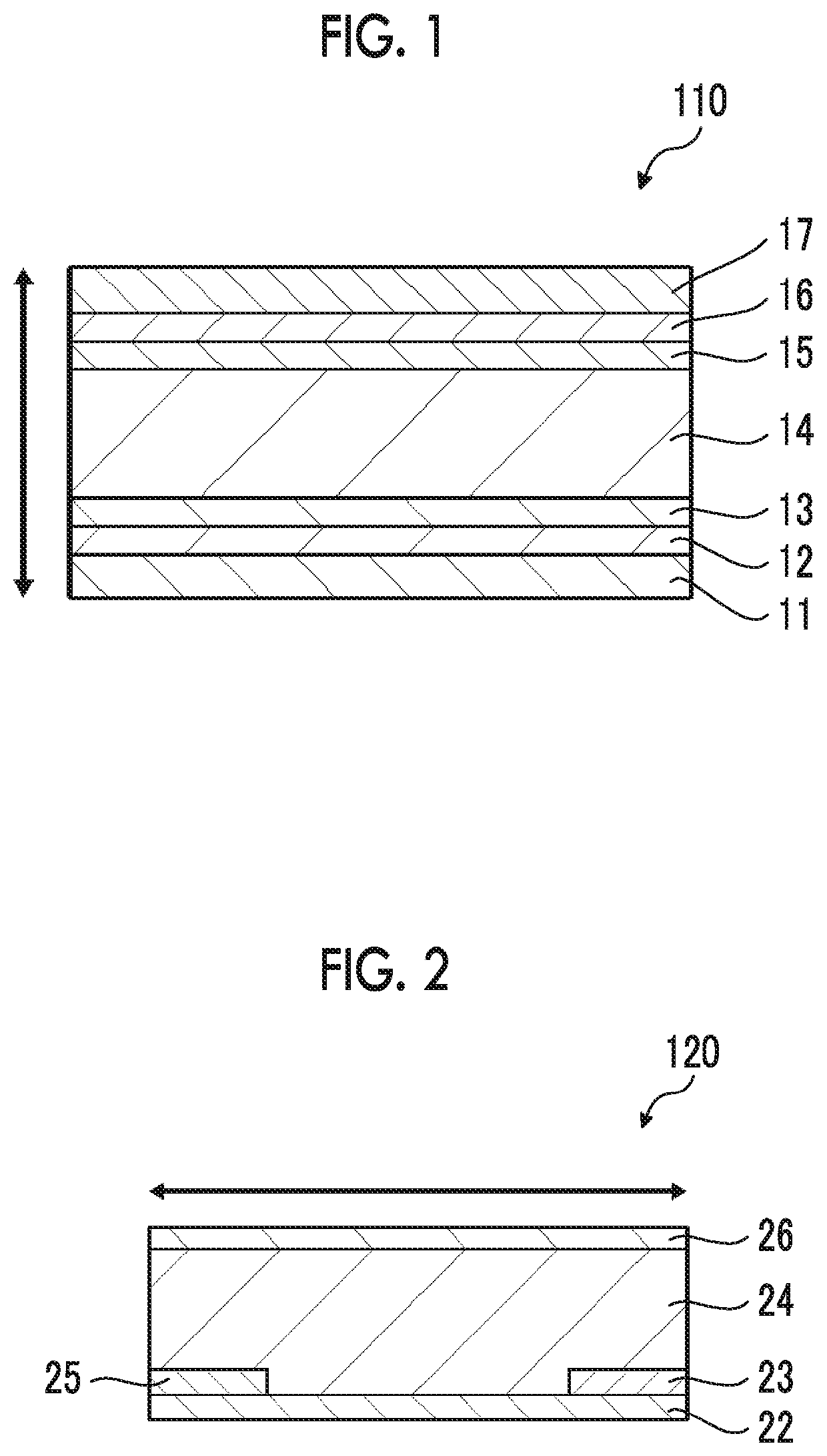
[0172]FIG. 1 is a cross-sectional view of a first embodiment of the thermoelectric conversion element of the present invention.

[0173]A thermoelectric conversion element 110 shown in FIG. 1 comprises a first substrate 12, a pair of electrodes including a first electrode 13 and a second electrode 15 on the first substrate 12, and a thermoelectric conversion layer 14 which is between the first electrode 13 and the second electrode 15 and contains the specific single-layer CNT and the specific dopant. On the other surface of the second electrode 15, a second substrate 16 is disposed. On the outside of the first substrate 12 and the second substrate 16, metal plates 11 and 17 facing each other are disposed.

second embodiment

[0174]FIG. 2 is a cross-sectional view of a second embodiment of the thermoelectric conversion element of the present invention.

[0175]A thermoelectric conversion element 120 shown in FIG. 2 is provided with a first substrate 22, a first electrode 23 and a second electrode 25 on the first substrate 22, and a thermoelectric conversion layer 24 which is on the electrodes and contains the specific single-layer CNT and the specific dopant. The other surface of the thermoelectric conversion layer 24 is provided with a second substrate 26.

third embodiment

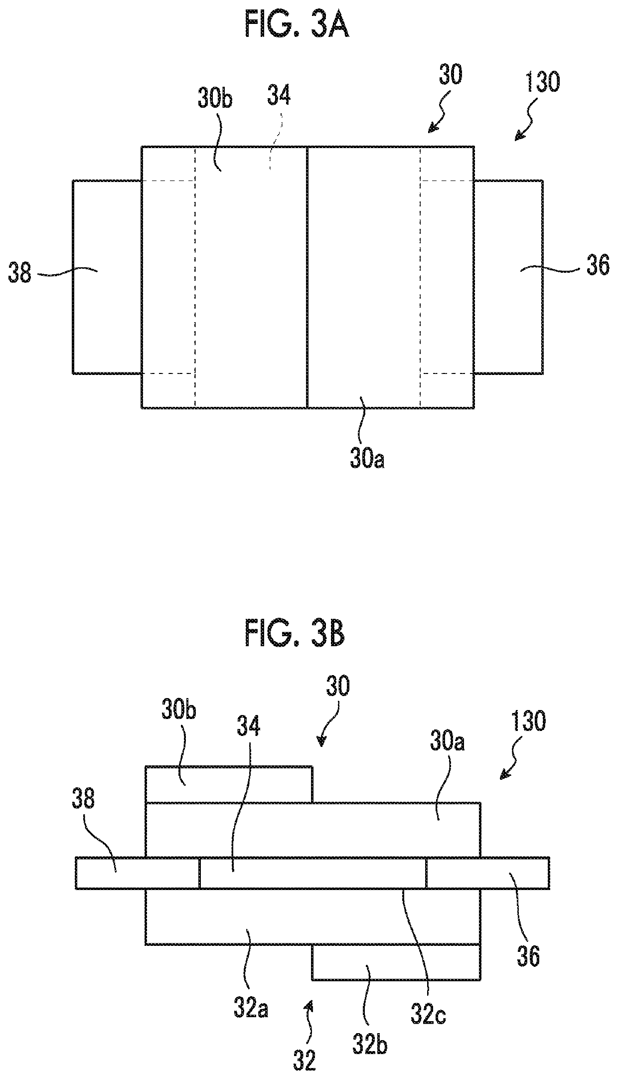
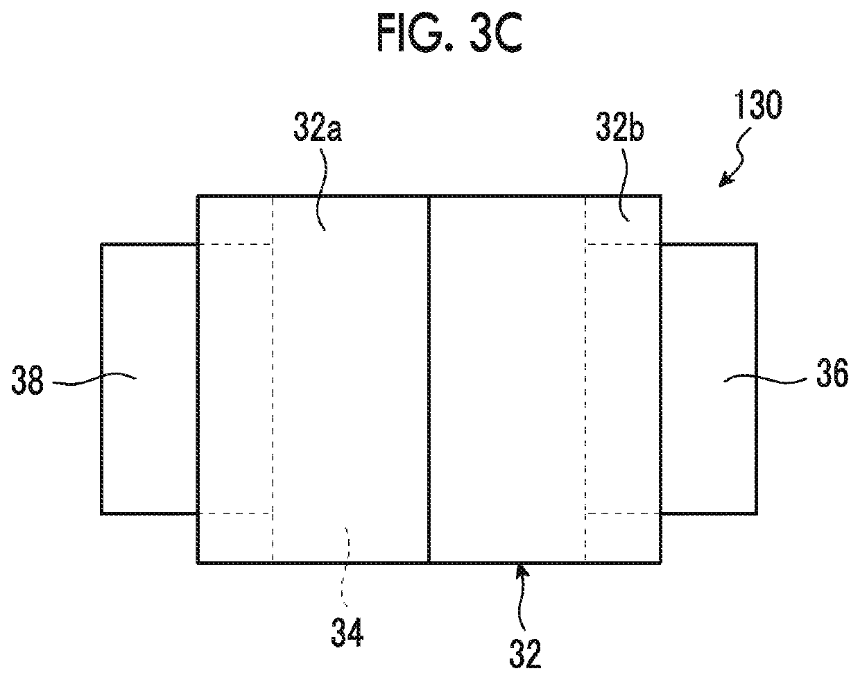
[0176]FIGS. 3A to 3C conceptually show a third embodiment of the thermoelectric conversion element of the present invention. FIG. 3A is a top view (a drawing obtained in a case where FIG. 3B is viewed from above the paper), FIG. 3B is a front view (a drawing obtained in a case where the thermoelectric conversion element is viewed from the plane direction of a substrate, which will be described later, and the like), and FIG. 3C is a bottom view (a drawing obtained in a case where FIG. 3B is viewed from the bottom of the paper).

[0177]As shown in FIGS. 3A to 3C, a thermoelectric conversion element 130 is basically constituted with a first substrate 32, a thermoelectric conversion layer 34 containing the specific single-layer CNT and the specific dopant, a second substrate 30, a first electrode 36, and a second electrode 38.

[0178]Specifically, on a surface of the first substrate 32, the thermoelectric conversion layer 34 is formed. Furthermore, on the surface of the first substrate 32, ...


PUM

PropertyMeasurementUnit
oxidation-reduction potentialaaaaaaaaaa
thermoelectricaaaaaaaaaa
semiconductingaaaaaaaaaa

Abstract

An object of the present invention is to provide a thermoelectric conversion layer having excellent thermoelectric conversion performances (particularly, a power factor and a figure of merit Z). Another object of the present invention is to provide a composition for forming a thermoelectric conversion layer that is used for forming the thermoelectric conversion layer, and a thermoelectric conversion element and a thermoelectric conversion module including the thermoelectric conversion layer.
The thermoelectric conversion layer according to an embodiment of the present invention is a thermoelectric conversion layer containing single-layer carbon nanotubes and a dopant, in which the single-layer carbon nanotubes contain semiconducting single-layer carbon nanotubes at a ratio equal to or higher than 95% and have a G/D ratio equal to or higher than 40, and the dopant is an organic dopant having a non-onium salt structure and has an oxidation-reduction potential equal to or higher than 0 V with respect to a saturated calomel electrode.

Description

CROSS-REFERENCE TO RELATED APPLICATIONS[0001]This application is a Continuation of PCT International Application No. PCT / JP2018 / 007526 filed on Feb. 28, 2018, which claims priority under 35 U.S.C. § 119(a) to Japanese Patent Application No. 2017-037253 filed on Feb. 28, 2017. The above application is hereby expressly incorporated by reference, in its entirety, into the present application.BACKGROUND OF THE INVENTION1. Field of the Invention[0002]The present invention relates to a thermoelectric conversion layer, a composition for forming a thermoelectric conversion layer, a thermoelectric conversion element, and a thermoelectric conversion module.2. Description of the Related Art[0003]Thermoelectric conversion materials that enable the interconversion of thermal energy and electric energy are used in power generating elements generating electric power from heat or thermoelectric conversion elements such as a Peltier element. Thermoelectric conversion elements can convert thermal ene...

Claims


Application Information

Patent Timeline
Patent Type & Authority Applications(United States)
IPC IPC(8): H01L35/22H01L35/24H01L35/04
CPCH01L35/04H01L35/24H01L35/22B82Y30/00C01B32/159H10N10/81H10N10/856H10N10/855H10K99/00
Inventor SUGIURA, HIROKIHAYASHI, NAOYUKINOMURA, KIMIATSU
Owner FUJIFILM CORP
Why Eureka
Try Eureka