Radar

a technology of a distance and a power supply, applied in the field of distance measurement, can solve the problems of narrowing the range of voltage vmin to vmax used, reducing and low resolving power, so as to improve the resolving power of a distance

Inactive Publication Date: 2006-06-27
FUJITSU GENERAL LTD
View PDF20 Cites 10 Cited by
  • Summary
  • Abstract
  • Description
  • Claims
  • Application Information

AI Technical Summary

Benefits of technology

[0008]An object of the invention is to provide a radar arranged so as to be able to improve resolving power of a distance.
[0010]According to the present invention, in the radar for measuring a distance corresponding to a time difference W1 between the time at which the transmission wave is transmitted and the time at which the received wave is received, on the occasion of conversion of the time difference W1 into the level of an electrical signal; e.g., a voltage or an electric current, a portion of the conversion characteristic of the conversion section involving a small time difference is set so as to become larger than a portion of the conversion characteristic of the conversion section involving a large time difference in terms of a change in the level of an electrical signal corresponding to the time difference. For instance, a predetermined first detection distance; e.g., a minimum detection distance, is designated by L1, and a longer predetermined second detection distance; e.g., a detection-necessary distance, is designated by L2. Within a first range S12 in which a time difference between L1 and L2 is small, rates of changes R1, R1a in the level of the electrical signal corresponding to a time difference W1 are set to large values. Therefore, within the range S12, the resolving power of a distance can be increased. Within a second range S23 which goes beyond the detection-necessary distance L2, is less frequently used, and has a large time difference, rates of changes R2, R2a are set to small values. As a result, the range in which the level of the electrical signal belonging to the first range S12 can be used is increased, thereby enabling an attempt to enhance resolving power.
[0011]The level of the thus-obtained electrical signal is converted into a digital value at uniform intervals through use of, e.g., an analog-to-digital converter, thereby computing a distance to the target. Thus, there is implemented a radar which enhances resolving power of a distance within the first range S12 from the minimum detection distance L1, which has a high degree of importance and is frequently used, to the detection-necessary distance L2. Therefore, the amount of change in the level of the electrical signal corresponding to the first range S12 is maximized, to thereby enhance the resolving power of a distance.
[0017]According to the present invention, a delay time ΔW1 pertaining to operation of an electrical circuit of either the transmission section or the receiving section or electrical circuits of both section is subtracted from the time difference W1 between the time at which the transmission wave is transmitted and the time at which the received wave is received, thereby determining a value W2. The level of the electrical signal corresponding to the thus-obtained value W2; that is, a voltage or an electrical current, is obtained. There is maximized a value—at which the level of the electrical signal corresponding to the time difference can change within the first range S12 from the minimum detection distance L1 to the detection-needed distance L2—thereby enhancing resolving power of a distance. A conversion characteristic for converting the value W2 obtained by subtraction into the level of the electrical signal may be such that the rate of a change remains constant over the entire range of the level of an electrical signal such as a convertible voltage of a distance computation section; e.g., an analog-to-digital converter. Preferably, as mentioned previously, the rates of changes R1, R1a are set to have values within the fist range S12 from the minimum detection range L1 to the detection-necessary distance L2. Within the second range S23 beyond the detection-necessary distance L2, the rates of changes R2, R2a are set to small values, whereby the resolving power of a distance can be enhanced to a much greater extent.
[0019]According to the present invention, the foregoing delay time is determined from a wraparound component formed as a result of the signal transmitted from the transmission section being received directly by the receiving section without being reflected from the target. Specifically, the delay time is set to a predetermined time which is longer than a period of time between the transmission time at which the transmission wave is transmitted and the receiving time at which the receiving section receives a wraparound component. Thus, an adverse effect of the wraparound component is prevented, and the resolving power of a distance can be enhanced by increasing the magnitude of changes in the level of the electrical signal within the first range S12.

Problems solved by technology

Accordingly, there arises a problem of low resolving power within the range of distance from the minimum detection distance L1, which is most frequently required, to a detection-necessary distance L2 (e.g., 10 to 20 m), which is a required distance; e.g., a distance required at the time of controlling of the vehicle's brake.
This also results in narrowing of the range of the voltage Vmin to Vmax used for detecting a distance, and consequently the resolving power of a distance falls further.

Method used


Image

  • Radar
  • Radar
  • Radar

Examples


Embodiment Construction

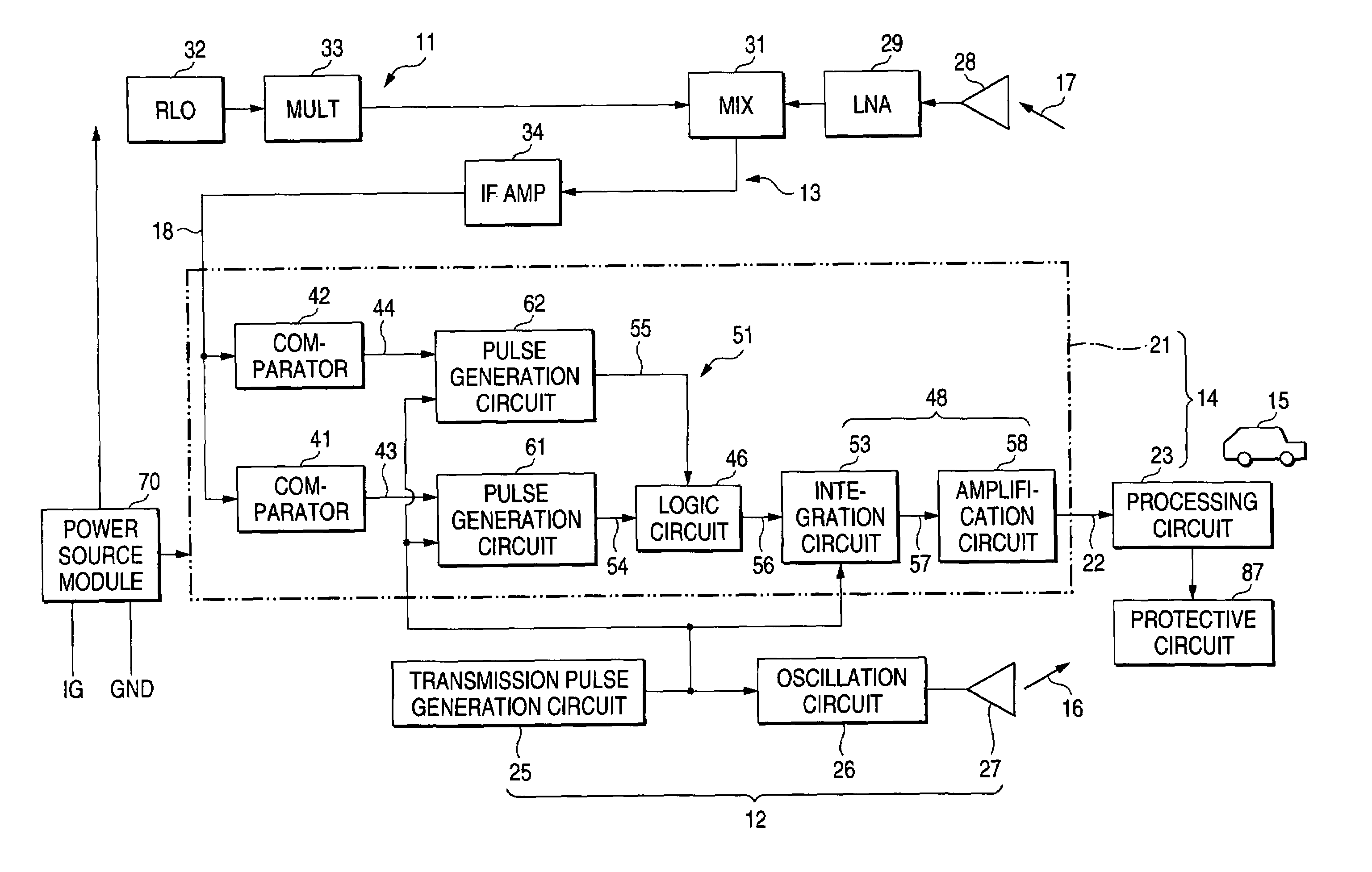
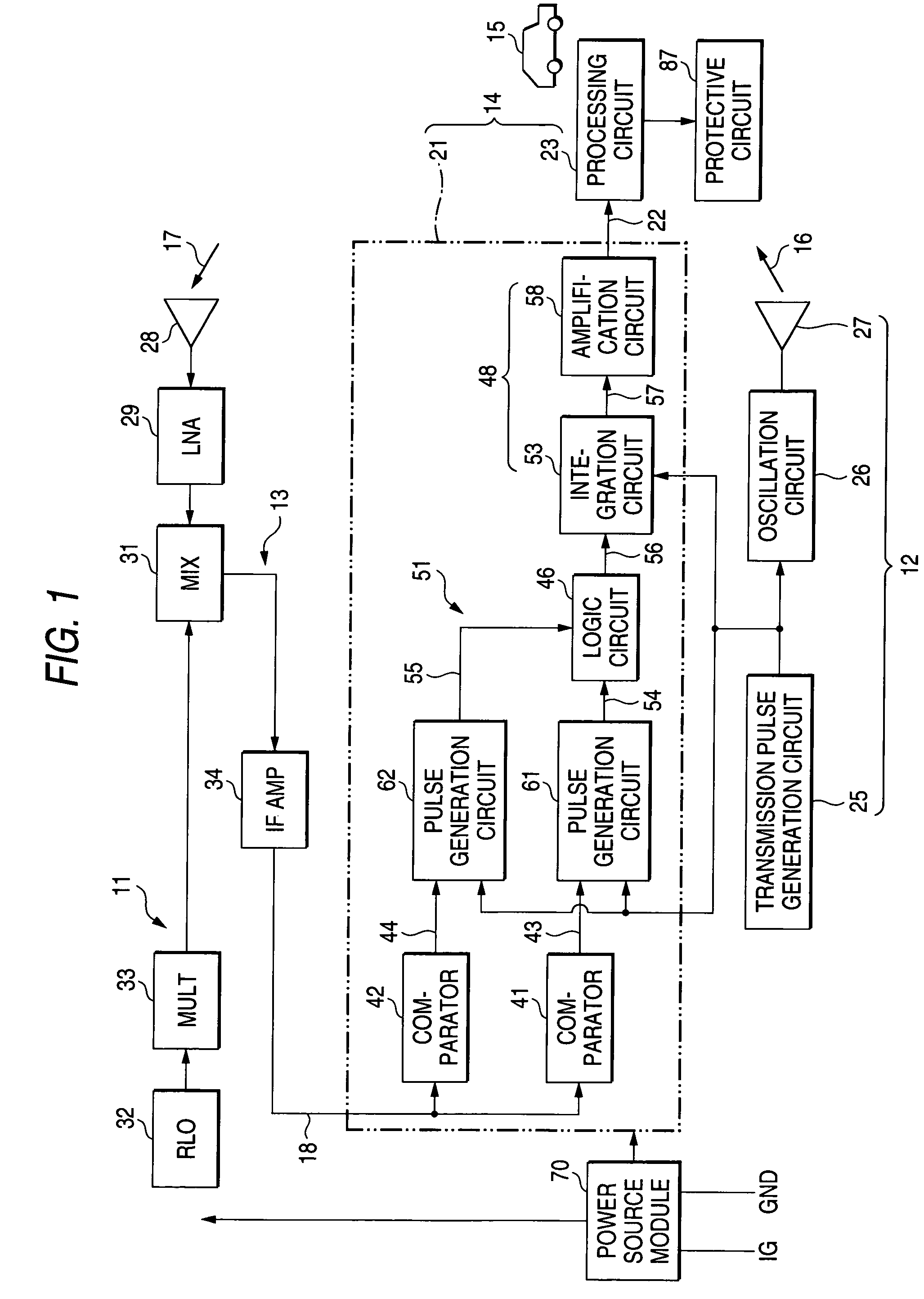
[0037]FIG. 1 is a block diagram showing the overall configuration of a radar 11 according to an embodiment of the invention. This radar is mounted on a vehicle, such as an automobile, and basically includes a transmission section 12, a receiving section 13, and a distance detection section 14. The transmission section 12 emits a transmission wave 16 forward. A wave 17 reflected by a target 15 (e.g., an automobile) is received by the receiving section 13, and a line 18 outputs the wave as a received wave. The distance detection section 14 includes a conversion section 21 and a processing circuit 23. The conversion section 21 converts a time difference W1 between the transmission time at which the transmission wave is transmitted and the receiving time at which the received wave is received into the level of an electrical signal; e.g., a voltage in the embodiment, through use of a predetermined conversion characteristic. A signal having a voltage corresponding to the time difference W...


PUM


Abstract

A transmission wave is transmitted to a target from a transmission section. A receiving section receives a wave reflected from the target as a received wave. A conversion section converts a time difference between the transmission time at which a transmission wave is transmitted and the receiving time at which a received wave is received in to a voltage. The thus-obtained voltage is subjected to analog-to-digital conversion by means of a processing circuit, whereby a distance is computed.

Description

BACKGROUND OF THE INVENTION[0001]1. Field of the Invention[0002]The present invention relates to a radar, and more particularly, to a radar which emits a transmission wave, such as a radio wave or light, to a target, receives a wave reflected from the target, and computes a distance between the radar and the target from a time difference.[0003]2. Description of the Related Art[0004]FIG. 13 is a view for describing operation of a typical radar in the related art. On the occasion of detection of a distance from the position of a radar to a target; e.g., a vehicle such as an automobile, a voltage level is obtained along with a conversion characteristic which varies in the form of a straight line within a range from L3 to L1 and is indicated by a line 1 shown in FIG. 13, provided that L3 designates a reflection limit distance which can be detected by the radar; e.g., 60 m, and that L1 designates a minimum detection distance L1; e.g., 0.5 m. The voltage obtained at the detectable distanc...

Claims


Application Information

Patent Timeline
Patent Type & Authority Patents(United States)
IPC IPC(8): G01S13/10G01S13/08G01S13/93G01S17/08G01S17/10G01S13/931G01S7/285
CPCG01S7/285G01S13/931G01S13/103
Inventor KAKISHITA, ETSUOYONEDA, KIMIHISA
Owner FUJITSU GENERAL LTD
Why Eureka
Try Eureka