System and method for electrostatic fly height control

a technology of electrostatic fly height and control method, applied in the direction of maintaining head carrier alignment, recording information storage, instruments, etc., can solve the problems of unfavorable transient mechanical contact between the head and the disc, damage to the head, the disc, or both, and the inability to control the fly heigh

Inactive Publication Date: 2006-06-27
SEAGATE TECH LLC
View PDF14 Cites 49 Cited by
  • Summary
  • Abstract
  • Description
  • Claims
  • Application Information

AI Technical Summary

Benefits of technology

[0006]The present invention relates to systems that address the above-mentioned problems. In one embodiment, a head for use in accessing data from an electrically conductive media surface is provided. The head includes a slider body defining a bearing plane configured to face the media surface. A fly height control electrode is positioned on the slider body and electrically isolated from the slider bo

Problems solved by technology

With these extremely small fly heights, manufacturing variations in the disc topography, particularly during seeking operations, can result in undesired transient mechanical contact between the head and the disc.
The electrostati

Method used


Image

  • System and method for electrostatic fly height control
  • System and method for electrostatic fly height control
  • System and method for electrostatic fly height control

Examples


Embodiment Construction

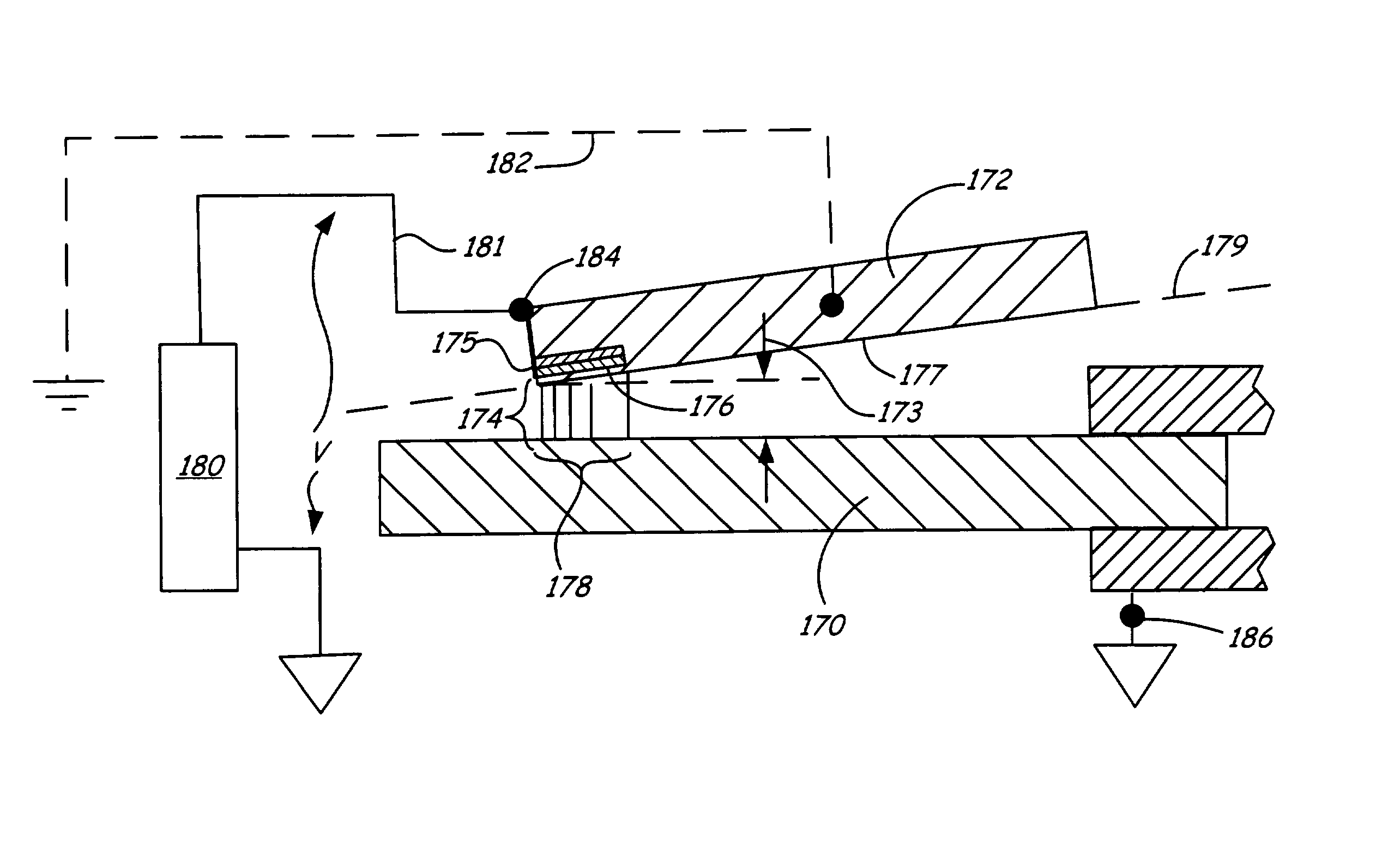
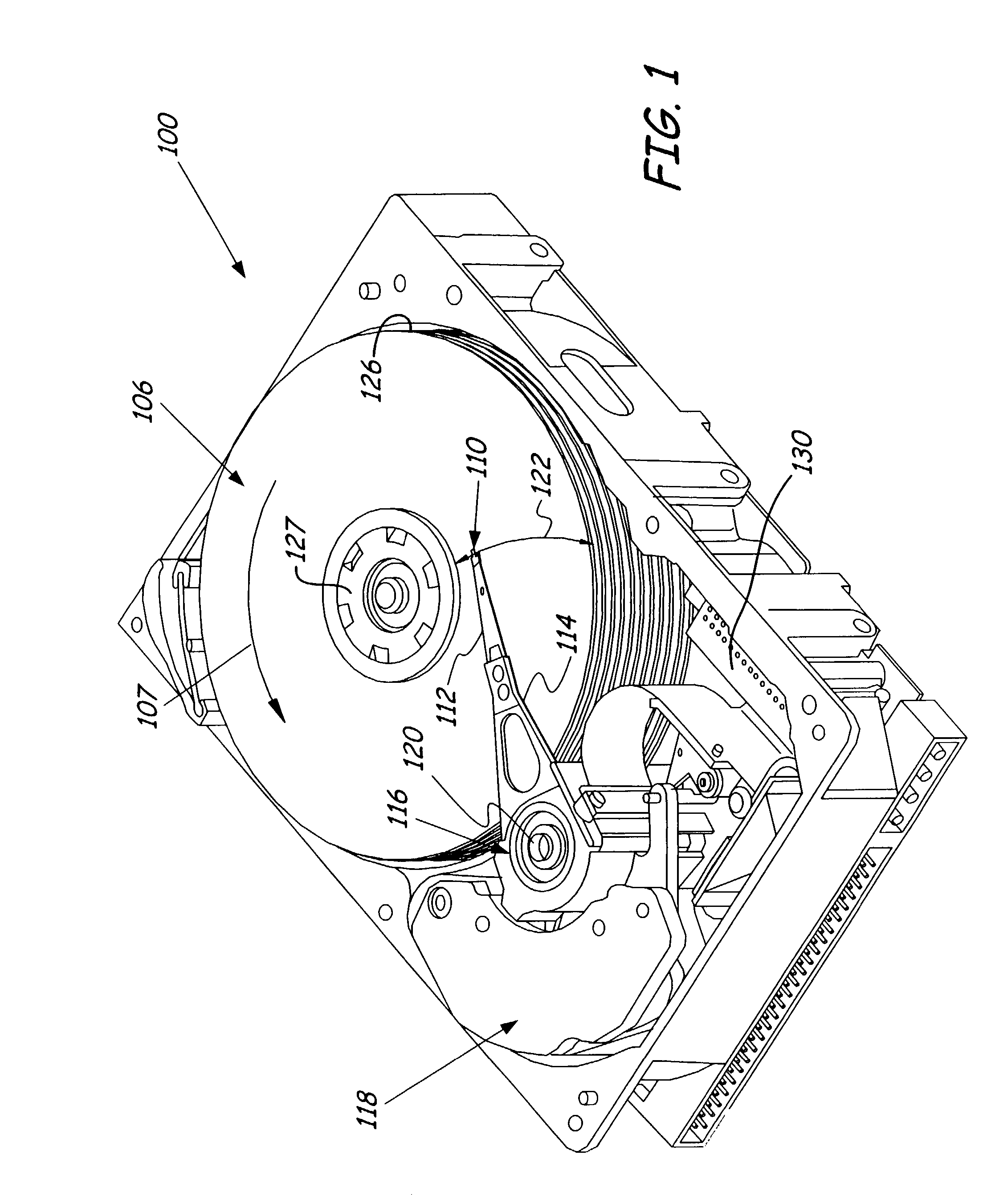
[0025]Embodiments of the present invention are useful in accessing data from a media surface. Accessing includes reading and / or writing data to a media surface. In the disc drive embodiments discussed below, fly height spacing between a head and a disc is controlled using a control signal voltage that electrostatically adjusts the fly height spacing to maintain fly height at a desired set point. When the spacing is extremely close, however, the control provided by the control circuit is unstable and the read / write head can be drawn into undesired contact with the disc by electrostatic attraction. The head includes an air-bearing surface and a dedicated fly height control electrode electrically isolated from the slider body. In one embodiment, a portion of the slider body provides a mechanical spacing between the electrode and the disc so that the electrode does not contact the disc. Furthermore, an electrostatic force between the electrode and the disc can be kept below certain leve...


PUM


Abstract

A head for use in accessing data from an electrically conductive media surface is provided. The head has a slider body defining a bearing plane configured to face the media surface. A fly height control electrode is positioned on the raised portion. Further, the fly height control electrode and the media surface are adapted to form opposing plates of a capacitor with a dielectric layer of air supporting the head. Also, the fly height control electrode is electrically isolated from the slider body. A head electrical connection disposed on the slider body is electrically connected to the fly height control electrode. The head electrical connection is adapted to provide a fly height control voltage to the fly height control electrode.

Description

CROSS-REFERENCE TO RELATED APPLICATION[0001]This application claims benefit of U.S. Provisional Application 60 / 314,521 titled “Contact Detection and Calibration for Electrostatic Fly Height Control in Disc Drive,” filed Aug. 22, 2001, U.S. Provisional Application 60 / 332,236 titled “Dedicated Electrodes for Electrostatic Fly Height Control,” filed Nov. 16, 2001 and U.S. Provisional Application 60 / 371,224 titled “Dedicated Electrode Concepts for Electrostatic Fly Height Control,” filed Apr. 9, 2002.FIELD OF THE INVENTION[0002]The present invention relates generally to magnetic data storage drives. In particular, this invention relates to methods and structures for fly height control.BACKGROUND OF THE INVENTION[0003]As the areal density in newer disc drive designs increases, the magnetic spacing and fly height between the pole tips of the read / write heads and the magnetic storage media becomes correspondingly smaller. With these extremely small fly heights, manufacturing variations in ...

Claims


Application Information

Patent Timeline
IPC IPC(8): G11B21/02G11B5/60G11B21/21
CPCG11B5/6005G11B5/581G11B5/6035
Inventor RIDDERING, JASON WAYNEBONIN, WAYNE ALLENSTOVER, LANCE EUGENEBOUTAGHOU, ZINE-EDDINEBURBANK, DANIEL PAUL
Owner SEAGATE TECH LLC
Why Eureka
Try Eureka