
Method of performing an area update for a terminal equipment in a communication network

a technology of communication network and area update, which is applied in the direction of wireless communication services, electrical equipment, wireless commuication services, etc., can solve the problems of double the address space, drop of calls, and failure of area update for a terminal equipment, so as to keep the amount of resulting changes small

Inactive Publication Date: 2006-06-27
NOKIA CORP
View PDF5 Cites 35 Cited by
  • Summary
  • Abstract
  • Description
  • Claims
  • Application Information

AI Technical Summary

Benefits of technology

[0019]Hence, the present invention provides an improved method of performing a routing area update for a terminal equipment in a communication network, which is suitable for a scenario in which it is required that a respective routing area has to be connectable to different core network elements of the same type, while still keeping the amount of resulting changes small.
[0034]Furthermore, as the identifier is carried as a part of the RAI this enables that no modifications are required to previously existing (“old”) core network elements.

Problems solved by technology

If, however, in the chosen example, a new SGSN does not know which previous SGSN to contact to retrieve the subscriber information of the requesting terminal equipment, a routing area update for a terminal equipment may fail and a call may be dropped.
However, assigning two identities inevitably doubles the address space for the routing areas, which is undesirable in terms of an additional need of network management in the core and access network.
Thus, this previously proposed solution requires multiple changes to the existing communication network.
However, as explained above, this assumption is no longer valid as a respective routing area is handled by several (different) network elements of the same network element type but of different core network types.

Method used


Image

  • Method of performing an area update for a terminal equipment in a communication network
  • Method of performing an area update for a terminal equipment in a communication network

Examples


Embodiment Construction

[0039]The present invention will now be explained in detail with reference to the drawings.

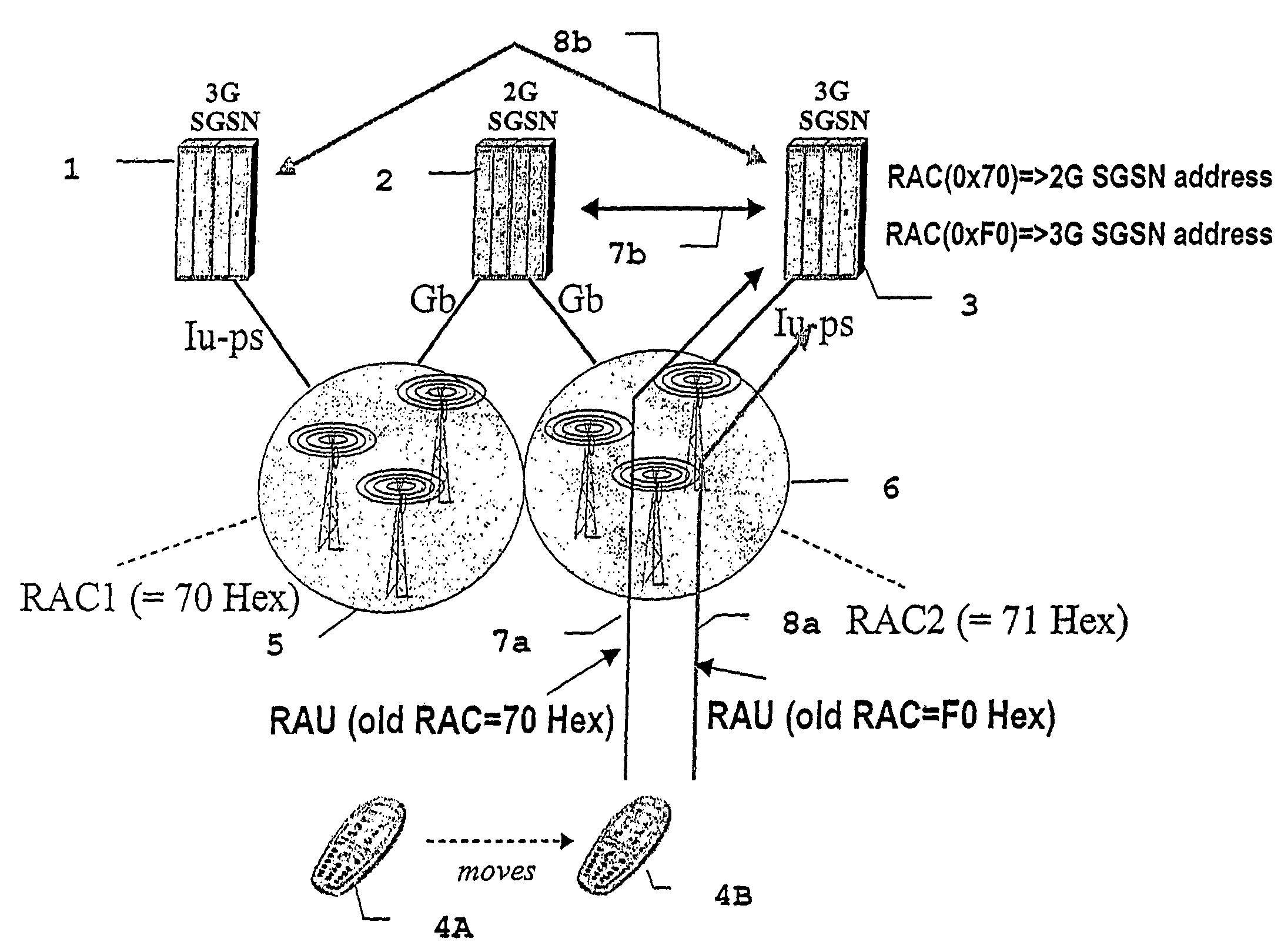
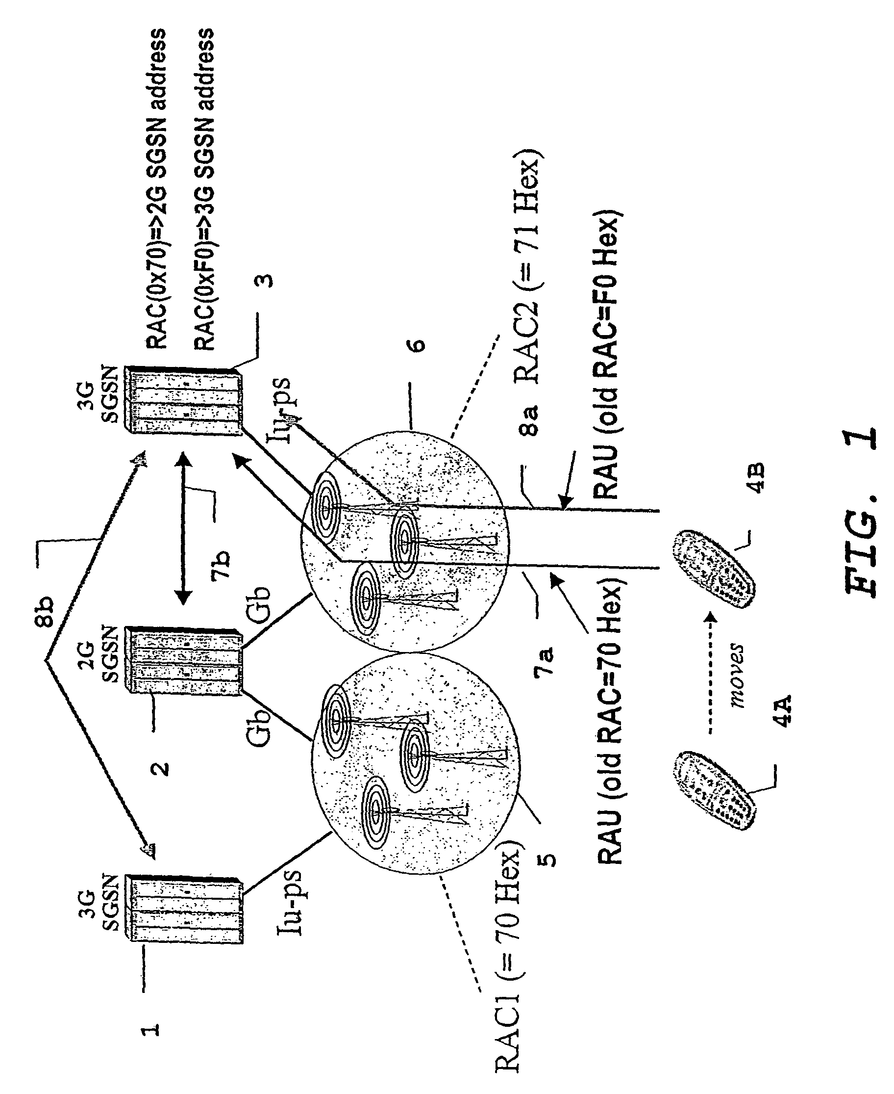
[0040]FIG. 1 illustrates a basic scenario of routing areas each connected to two core network elements of a same type but of respective different core networks, and a routing area update signaling involved in routing area update.

[0041]Nevertheless, it has to be noted that the cells of the new routing area do not necessarily have to be connected to two core network elements of a same type but of respective different core networks, rather it is sufficient for the present invention if at least one, that is only the previously visited, routing area to which registration has been performed is connected to two core network elements of a same type but of respective different core networks.

[0042]Firstly, the basic scenario will statically be described, that is without a focus to any signaling messages exchanged between the network elements.

[0043]FIG. 1 illustrates two routing areas 5 and 6, respective...


PUM


Abstract

The present invention proposes a method of performing an area update for a terminal equipment (4A, 4B) in a communication network (1, 2, 3, 5, 6), the communication network comprising at least two areas (5, 6) being defined within an access network, at least one of said areas being served by at least two core network elements (1-2, 2-3) of corresponding network element types, each of said at least two core network elements communicating with said access network defining said areas via a different interface (Iu, Gb), the method comprising the steps of: monitoring, at the terminal equipment side, via which of said at least two core network elements (1, 2) serving a currently visited area (5) the communication with the terminal equipment (4A) is effected, detecting, at the terminal equipment side, an area update condition for said terminal (4A, 4B), requesting, by said terminal equipment, an area update for said terminal equipment (4B), and wherein said terminal equipment (4B) sets an identifier in said area update request identifying the core network element via which the communication with the terminal equipment (4A) has previously been effected. Still further, the present invention proposes also an accordingly adapted terminal equipment.

Description

BACKGROUND OF THE INVENTION[0001]1. Field of the Invention[0002]The present invention relates to method of performing an area update for a terminal equipment in a communication network, and also to a correspondingly adapted terminal equipment.[0003]2. Description of the Prior Art[0004]Generally, communication networks consist of an access network and a core network. The access network is specifically adapted to a connection technology used for terminal equipment communicating with / via the network, whereas the core network is connection technology independent and manages the functions the network offers to the terminals registered in the network.[0005]Currently, for example, there exists the GSM network (GSM=Global Standard for Mobile Communication), consisting of a so called base station subsystem BSS as the access network part and the core network comprising e.g. the mobile services switching center MSC, a home location register HLR, visitor location register VLR etc. The base stat...

Claims


Application Information

Patent Timeline
IPC IPC(8): H04Q7/20H04W60/04H04W88/14H04W92/02H04W92/14H04W92/24
CPCH04W60/04H04W88/14H04W92/02H04W92/24H04W92/14
Inventor RAJANIEMI, JAAKKOHULKKONEN, TONY
Owner NOKIA CORP
Learn More