

Transceiver capable of causing series resonance with parasitic capacitance
a technology of parasitic capacitance and transceiver, which is applied in the field of transceivers, can solve the problems of wearing computers that can be worn on the living body and attract attention, and achieve the effect of preventing the decrease of voltage and improving communication quality
- Summary
- Abstract
- Description
- Claims
- Application Information
AI Technical Summary
Benefits of technology
Problems solved by technology
Method used
Image

Examples
first embodiment
[0059]Referring now to FIG. 4 to FIG. 16, a transceiver according to the present invention will be described in detail.
[0060]In the following description, the case where the wearable computer transmits data by inducing electric fields in the living body through a transceiver will be referred to as “data transmission time”, and the case where the wearable computer receives data detected from electric fields induced in the living body through a transceiver will be referred to as “data reception time”.
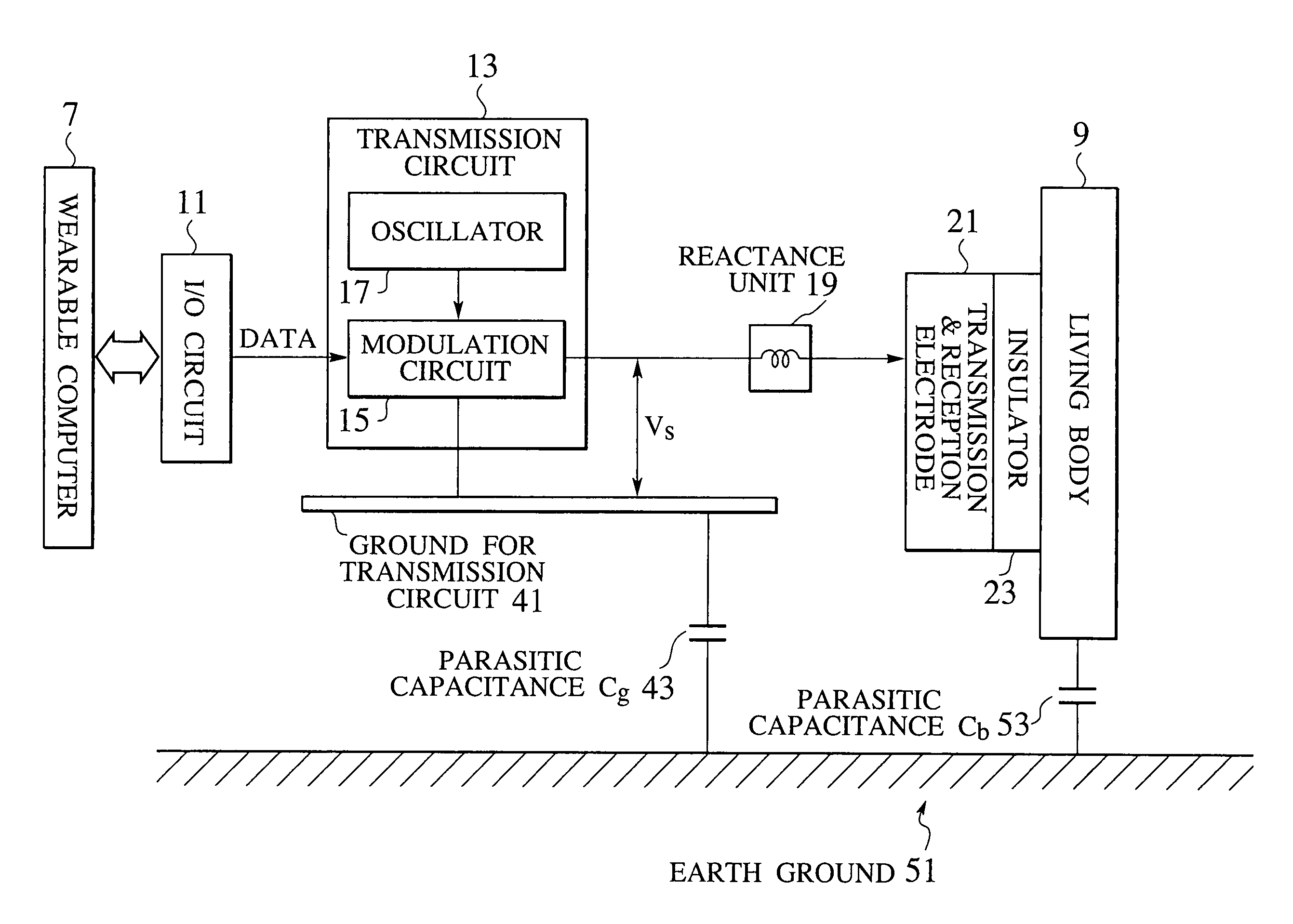
[0061]FIG. 4 shows a configuration of a main part of a transceiver according to the first embodiment. Note that FIG. 4 only shows a configuration common to all implementations of the transceiver according to the first embodiment, and further detailed configurations of the entire transceiver in various implementations will be described below.
[0062]The transceiver shown in FIG. 4 has at least an I / O circuit 11 for outputting data received from the wearable computer 7 while receiving receive...
second embodiment
[0158]Referring now to FIG. 17 to FIGS. 22A and 22B, a transceiver according to the present invention will be described in detail.
[0159]The transceiver of the first embodiment assumes that the phase of the reference signal outputted from the transmission circuit coincides with the phase of the output signal of the signal processing circuit. However, in the case where the delay caused by the electric field detecting optical unit or the signal processing circuit becomes unignorable compared with the period of the carriers, there is a possibility of causing a phase difference between the reference signal and the output signal of the signal processing circuit. In fact, there is a possibility for this phase difference problem to become noticeable as in the case where the frequency of the carriers becomes high and give rise to unignorable influences.
[0160]For this reason, this second embodiment provides a transceiver capable of preventing the decrease of the voltage applied to the electri...
third embodiment
[0231]Referring now to FIG. 23 to FIGS. 30A and 30B, a transceiver according to the present invention will be described in detail.
[0232]In the transceiver of the first embodiment, the instantaneous values of the output voltage Vs of the transmission circuit and the voltage Vb applied to the living body are compared in order to be capable of applying any modulation scheme, but this comparison method has a problem that it is vulnerable to the delay or the signal distortion that may occur in the circuit. For this reason, in order to carry out the processing without the signal delay or the waveform distortion, the wide bandwidth and the high linearity are required not only to the amplitude monitoring unit but also to the amplifier, etc. used in the signal processing circuit, and these circuits in turn require expensive components.
[0233]For this reason, this third embodiment provides a transceiver capable of preventing the decrease of the voltage applied to the electric field propagating...
PUM
 Abstract
Description
Claims
Application Information