
High strength, lightweight blow-molded plastic structures

a technology of lightweight, high-strength, and blow-molded plastics, which is applied in the field of high-strength, lightweight blow-molded plastic structures, can solve the problems of inability to support a relatively large amount of weight or force, many known blow-molded structures are relatively low-strength, and many blow-molded structures are not high-strength

Active Publication Date: 2006-07-04
LIFETIME PRODUCTS
View PDF30 Cites 155 Cited by
  • Summary
  • Abstract
  • Description
  • Claims
  • Application Information

AI Technical Summary

Benefits of technology

The present invention relates to structures made from blow-molded plastic that have increased strength and can be used for various applications such as tables, chairs, and sports equipment. The structures have increased strength because they have more depressions, which increase the surface area and allow for a thinner outer wall. This reduces the amount of plastic required to construct the structure and decreases the manufacturing time. The increased number of depressions also allows for faster cooling and reduces the weight of the structure. The depressions are preferably uniformly spaced to create consistent and standardized arrangements. The structures have a lower profile because reinforcing ribs are not required. Overall, the invention provides stronger, lighter, and more efficient structures made from blow-molded plastic.

Problems solved by technology

Because blow-molded structures include a hollow interior space, many blow-molded structures are not high-strength.
In fact, many known blow-molded structures are relatively low-strength and are unable to support a relatively large amount of weight or force.
Disadvantageously, the metal ribs must be attached to the table top by mechanical fasteners such as bolts or screws.
The bolts or screws require holes in the table top, which may create stress concentrations and / or potential failure points in the table top.
Alternatively, the metal ribs may be attached to the table top by adhesives, but the adhesives may also decrease the structural integrity of the table top and make the table top very difficult to repair or replace.
In addition, the metal ribs increase the number of components required to construct the table and increase the time required to manufacture the table.
Thus, while it is known to use metal ribs to increase the strength of a blow-molded table top, metal ribs undesirably increase the time and costs to manufacture the table.
Further, the attachment of the metal ribs to the table top may decrease the strength and / or structural integrity of the table top, and increase the potential causes of failure of the table.
Disadvantageously, the thicker outer walls of the ribs require additional plastic materials be used to create the table tops, which increases the costs and weight of the table tops.
This undesirably increases the time of the manufacturing process because the blow-molded table tops cannot be removed from the mold until the tops are sufficiently cooled.
Disadvantageously, the large, protruding ribs may undesirably decrease the amount of room underneath the table top and limit the potential design considerations for the table top.
Conventional table tops constructed from blow-molded plastic and including strengthening ribs may still not have sufficient strength and may allow a portion of the table top to sag.
These additional ribs require a larger area on the underside of the table top, which limits the area that other features may be formed in the table top.
The plurality of strengthening ribs may also interfere with other desired features or components of the table, such as interfering with the folding of the table legs into a collapsed position.
The ribs may also further increase the cooling time and manufacturing time of the table top.
Thus, the upper surface of the table top may be uneven because different portions of the table top are supported differently.

Method used


Image

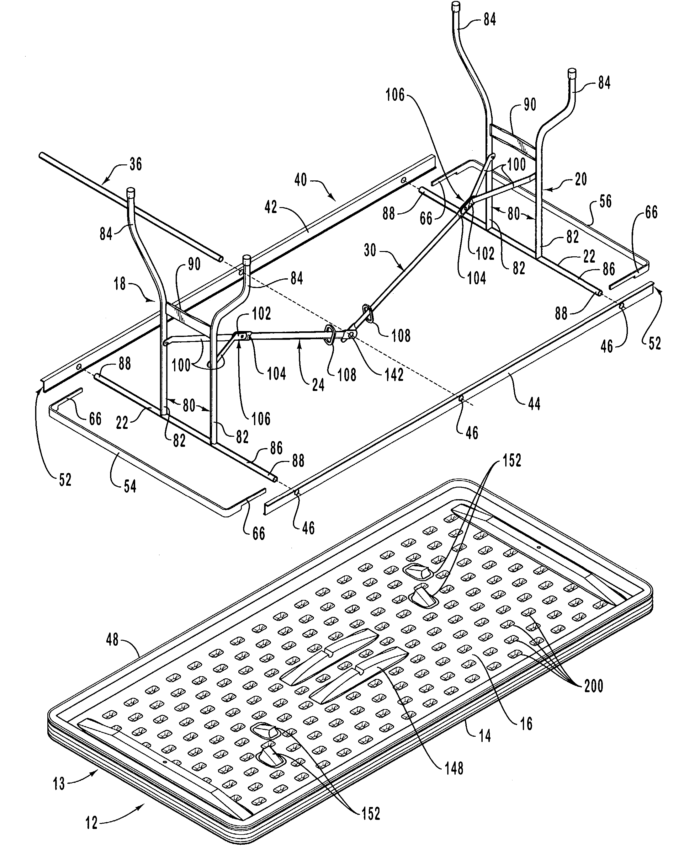
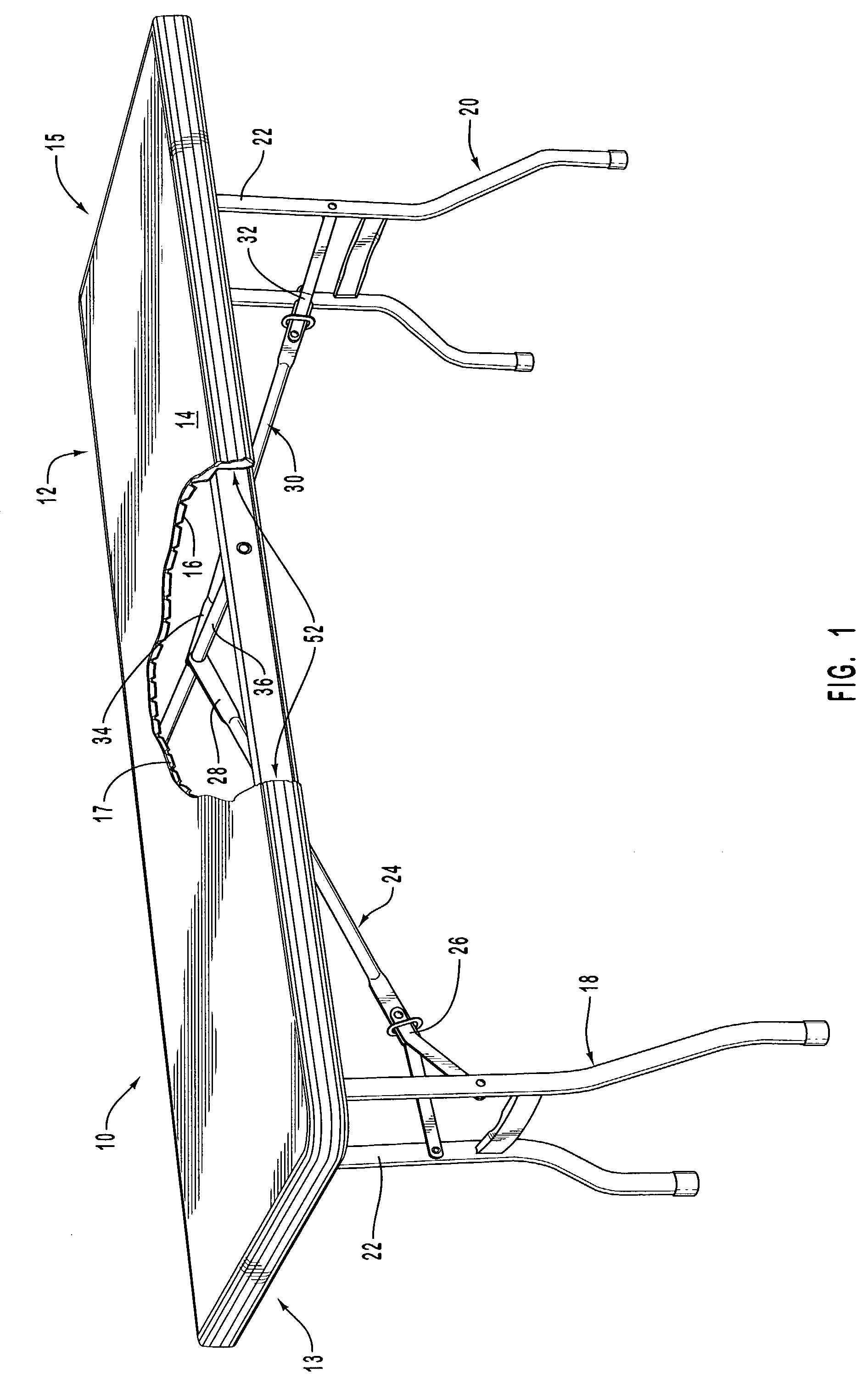
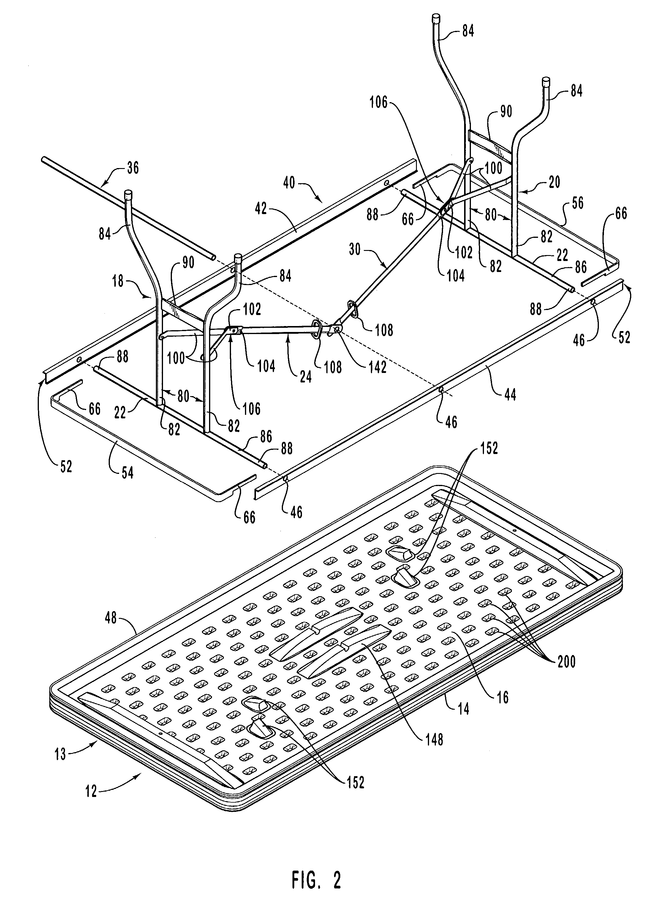
  • High strength, lightweight blow-molded plastic structures
  • High strength, lightweight blow-molded plastic structures
  • High strength, lightweight blow-molded plastic structures

Examples


Embodiment Construction

[0034]This invention is generally directed towards blow-molded structures that have increased strength and / or are lighter weight. The principles of the present invention, however, are not limited to blow-molded structures with increased strength and lighter weight. It will be understood that, in light of the present disclosure, the blow-molded structures which are disclosed herein can be successfully used in connection with other types of blow-molded structures that do not have increased strength or lighter weight.

[0035]Additionally, to assist in the description of the blow-molded structures, words such as top, bottom, front, rear, right and left are used to describe the accompanying figures. It will be appreciated, however, that the blow-molded structures can be located in a variety of desired positions—including various angles, sideways and even upside down. A detailed description of the blow-molded structures that may have increased strength and / or are lighter weight now follows....


PUM

PropertyMeasurementUnit
angleaaaaaaaaaa
angleaaaaaaaaaa
angleaaaaaaaaaa

Abstract

Blow molded plastic structures are provided for use in various structures such as, but not limited to, tables, chairs, walls, backboards, storage bins, sports equipment and the like. The blow molded plastic structure has a first surface and a second surface extending between a first end and a second end and forming a chamber there between. A plurality of depressions is formed on the second surface and extends into the chamber. The depressions are usually unitary structures formed by a depression wall. Generally, the steeper the depression wall, the more strength is provided to the structure. In addition, where the plurality of depressions has a low profile and a greater density, increased strength is provided to the structure. The depressions may or may not be joined to the first surface.

Description

CROSS-REFERENCE TO RELATED APPLICATIONS[0001]This application claims priority to and the benefit of U.S. Provisional Patent Application Ser. No. 60 / 371,486, entitled UTILITY TABLE WITH BLOW-MOLDED TABLE TOP, which was filed on Apr. 9, 2002, and is hereby incorporated by reference in its entirety.BACKGROUND OF INVENTION[0002]1. Field of Invention[0003]The present invention generally relates to structures constructed from blow-molded plastic and, in particular, to high-strength, lightweight blow-molded plastic structures.[0004]2. Description of Related Art[0005]It is known to construct various objects and items, such as tables, chairs, partitions, walls, and sports equipment, from plastic. It is also known to construct some of these and other objects from blow-molded plastic. As known to those skilled in the art, blow-molded structures include an outer wall that encloses a hollow interior space. Because blow-molded structures include a hollow interior space, many blow-molded structure...

Claims


Application Information

Patent Timeline
Patent Type & Authority Patents(United States)
IPC IPC(8): A47B3/00A47B3/087A47B3/091A47B13/00A47B13/08A63B63/08B29C49/00F16B12/24
CPCA47B3/087A47B3/0912A47B13/003A47B13/08A63B63/083B29C49/0031F16B12/24A47B3/091Y10T428/1397B29C49/04B29C49/4802B29K2995/0077B29K2995/0082B29K2995/0089B29L2031/448B29L2031/52Y10T428/24355
Inventor STRONG, L. CURTISMOWER, BARRY D.
Owner LIFETIME PRODUCTS
Learn More