
Air supply unit for an internal combustion engine

a technology for air supply units and internal combustion engines, which is applied in the direction of combustion engines, combustion-air/fuel-air treatment, and charge feed systems, etc., can solve the problems of obvious increase in cost and complexity of air supply units, and it is extremely difficult to gain access to individual butterfly valves in order to regulate, so as to achieve simple and economic effect of implementation

Inactive Publication Date: 2006-07-04
FAB ITAL MAGNETI MARELLI SPA
View PDF6 Cites 4 Cited by
  • Summary
  • Abstract
  • Description
  • Claims
  • Application Information

AI Technical Summary

Benefits of technology

"The present invention provides an air supply unit for an internal combustion engine that is simple and economical to implement. The unit does not have the disadvantages of previous designs."

Problems solved by technology

According to some design philosophies for internal combustion engines, each engine cylinder is provided with a respective butterfly valve; however, this design approach is associated with some disadvantages, in that once the engine is installed in the respective vehicle, it is extremely difficult to gain access to the individual butterfly valves in order to regulate them, both during vehicle assembly and during periodic maintenance of the vehicle.
Moreover, providing each cylinder with a respective butterfly valve brings about an obvious increase in the cost and complexity of the air supply unit because of the greater number of components in the air supply unit itself.

Method used


Image

  • Air supply unit for an internal combustion engine
  • Air supply unit for an internal combustion engine
  • Air supply unit for an internal combustion engine

Examples


Embodiment Construction

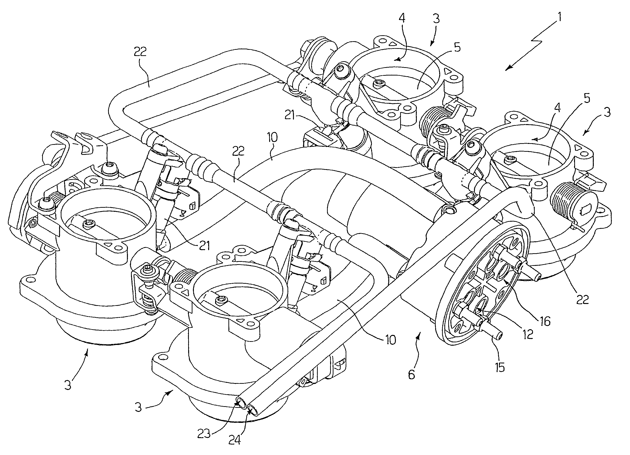
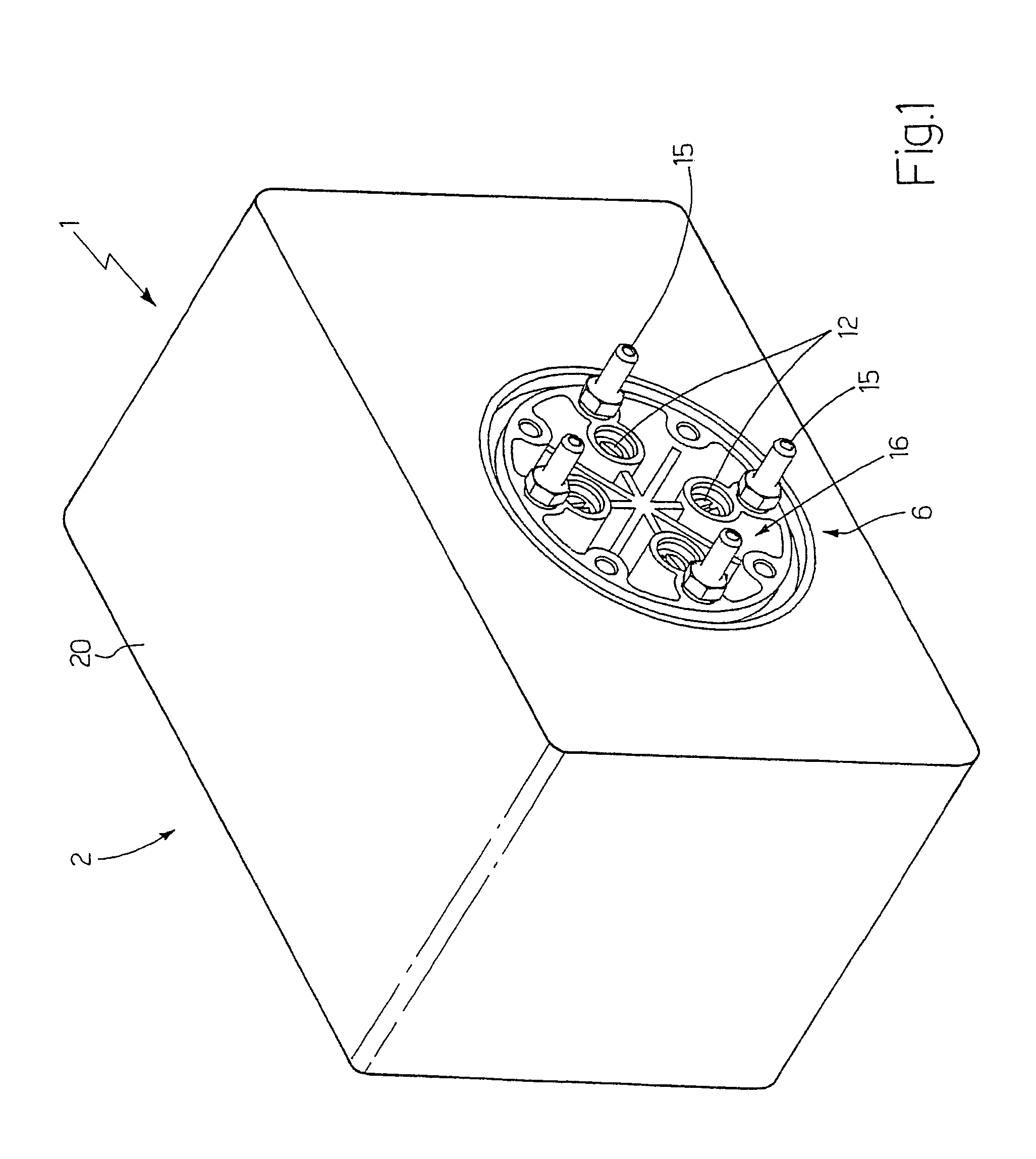
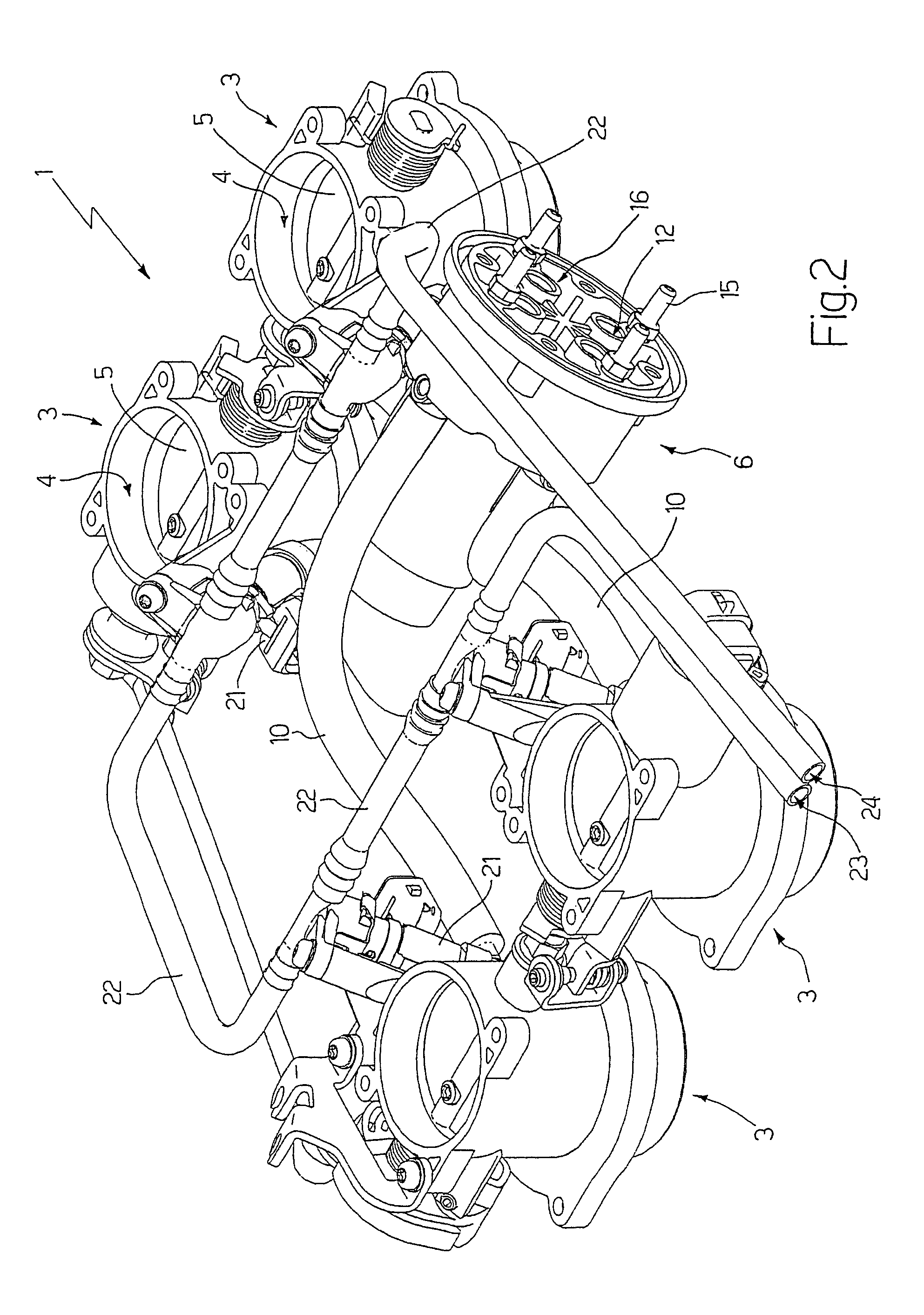
[0012]In FIGS. 1 and 2, the reference number 1 indicates, as a whole, an air supply unit for an internal combustion engine (not shown), said engine being provided with four cylinders (not shown) arranged in a “V” configuration.

[0013]The air supply unit 1 comprises an intake box 2 (also known as an “air box”) which is in communication with the external environment through an air filter (not shown in detail), and four butterfly valves 3, each of which is connected to a corresponding engine cylinder; each butterfly valve 3 has its own internal duct 4, which is interposed between the intake box 2 and the intake duct of a corresponding cylinder and is regulated by a butterfly disc 5, which oscillates between a closed position and a maximally open position of said internal duct 4.

[0014]As shown in particular in FIGS. 2 and 4, the air supply unit 1 comprises a distributor device 6, which is provided with a chamber 7 connected to the intake box 2 by means of an air duct 8 (shown in dashed l...


PUM


Abstract

An air supply unit for an internal combustion engine; the air supply unit is provided a number of butterfly valves and a distributor device, the latter being provided, for each butterfly valve, with a distribution duct capable of placing an internal duct of said butterfly valve in communication with a chamber of the distributor device connected to an intake box by means of a first air duct regulated by a solenoid valve; inside the distributor device, each distribution duct is connected to the intake box by means of a corresponding second air duct regulated by a respective bypass screw and is connected to a corresponding regulation duct opening into an air intake, which is accessible from the outside of the distributor device and is normally closed by an associated removable plug.

Description

[0001]The present invention relates to an air supply unit for an internal combustion engine.BACKGROUND OF THE INVENTION[0002]An internal combustion engine usually has an air supply unit composed of an intake box (also known as an “air box”) which is in communication with the external environment by means of a respective air filter and at least one butterfly valve interposed between the intake box and the intake ducts of the cylinders in order to regulate the flow rate of the air supplied to the cylinders themselves.[0003]According to some design philosophies for internal combustion engines, each engine cylinder is provided with a respective butterfly valve; however, this design approach is associated with some disadvantages, in that once the engine is installed in the respective vehicle, it is extremely difficult to gain access to the individual butterfly valves in order to regulate them, both during vehicle assembly and during periodic maintenance of the vehicle. Moreover, providin...

Claims


Application Information

Patent Timeline
Patent Type & Authority Patents(United States)
IPC IPC(8): F02B13/00F02D9/10F02M35/10
CPCF02D9/109F02M35/10032F02D9/1055F02M35/108F02M35/10216
Inventor GAMBERINI, GIUSEPPECAVRINI, ALESSANDRO
Owner FAB ITAL MAGNETI MARELLI SPA
Learn More