Method and system for the direct injection of fuel into an internal combustion engine

a technology of fuel injection and internal combustion engine, which is applied in the direction of fuel injection apparatus, machine/engine, charge feed system, etc., can solve the problems of low energy efficiency of known injection system, system overheating of fuel, and “pointless” work performed by the high-pressure pump in pumping fuel that is subsequently discharged by the pressure regulator, etc., to achieve simple and economic effect of implementation

Active Publication Date: 2007-04-03
FAB ITAL MAGNETI MARELLI SPA
View PDF23 Cites 12 Cited by
  • Summary
  • Abstract
  • Description
  • Claims
  • Application Information

AI Technical Summary

Benefits of technology

[0015]The aim of the present invention is to provide a method and a system for the direct injection of fuel into an internal combustion engine, which method and system do not have the above-described disadvantages and, in particular, are simple and economic to implement.

Problems solved by technology

Known injection systems of the type described above have various disadvantages, because the high-pressure pump must be dimensioned so as to supply the common rail with a quantity of fuel that slightly exceeds the maximum possible consumption; however, this maximum possible consumption state occurs relatively rarely and in all other operating states the quantity of fuel supplied to the common rail by the high-pressure pump is much greater than that actually consumed and thus a considerable proportion of said fuel must be discharged by the pressure regulator into the recirculation channel.
Obviously, the work performed by the high-pressure pump in pumping fuel that is subsequently discharged by the pressure regulator is “pointless” work and such known injection systems accordingly have very low energy efficiency.
Moreover, such known injection systems have a tendency to overheat the fuel, because when the excess fuel is discharged by the pressure regulator into recirculation channel, said fuel passes from a very high pressure (greater than 1000 bar) to a substantially ambient pressure and this pressure drop tends to increase the temperature of the fuel.
Finally, known injection systems of the type described above are relatively bulky owing to the presence of the pressure regulator and the recirculation channel connected to the pressure regulator.
The disparity described above, which arises between the two injectors performing the injection phase during the same revolution of the drive shaft results in a disparity in the quantity of fuel injected by the two injectors with an identical injection time, with obvious repercussions on the correct operation of the engine; moreover, this disparity does not always occur to the same extent, but there is a substantial difference when the flow rate required from the high-pressure pump is lower than a certain threshold value corresponding to the value at which choking of the high-pressure pump coincides with the beginning of the injection phase of the first injector to inject, out of the two injectors performing the injection phase during the same revolution of the drive shaft.
Moreover, making the pistons of the high-pressure pump perform one cycle (i.e. an intake stroke and a pumping stroke) on each revolution of the drive shaft instead of one cycle every two revolutions of the drive shaft entails doubling the average velocity of said pistons with obvious problems of mechanical strength and reliability over time.
Alternatively, it has been proposed to use high-pressure pumps equipped with four cylinders and thus with four pistons, each of which performs one cycle every two revolutions of the drive shaft; however, while this solution is more straightforward to implement, it involves substantially higher costs and bulkiness of the high-pressure pump.

Method used


Image

  • Method and system for the direct injection of fuel into an internal combustion engine
  • Method and system for the direct injection of fuel into an internal combustion engine
  • Method and system for the direct injection of fuel into an internal combustion engine

Examples


Embodiment Construction

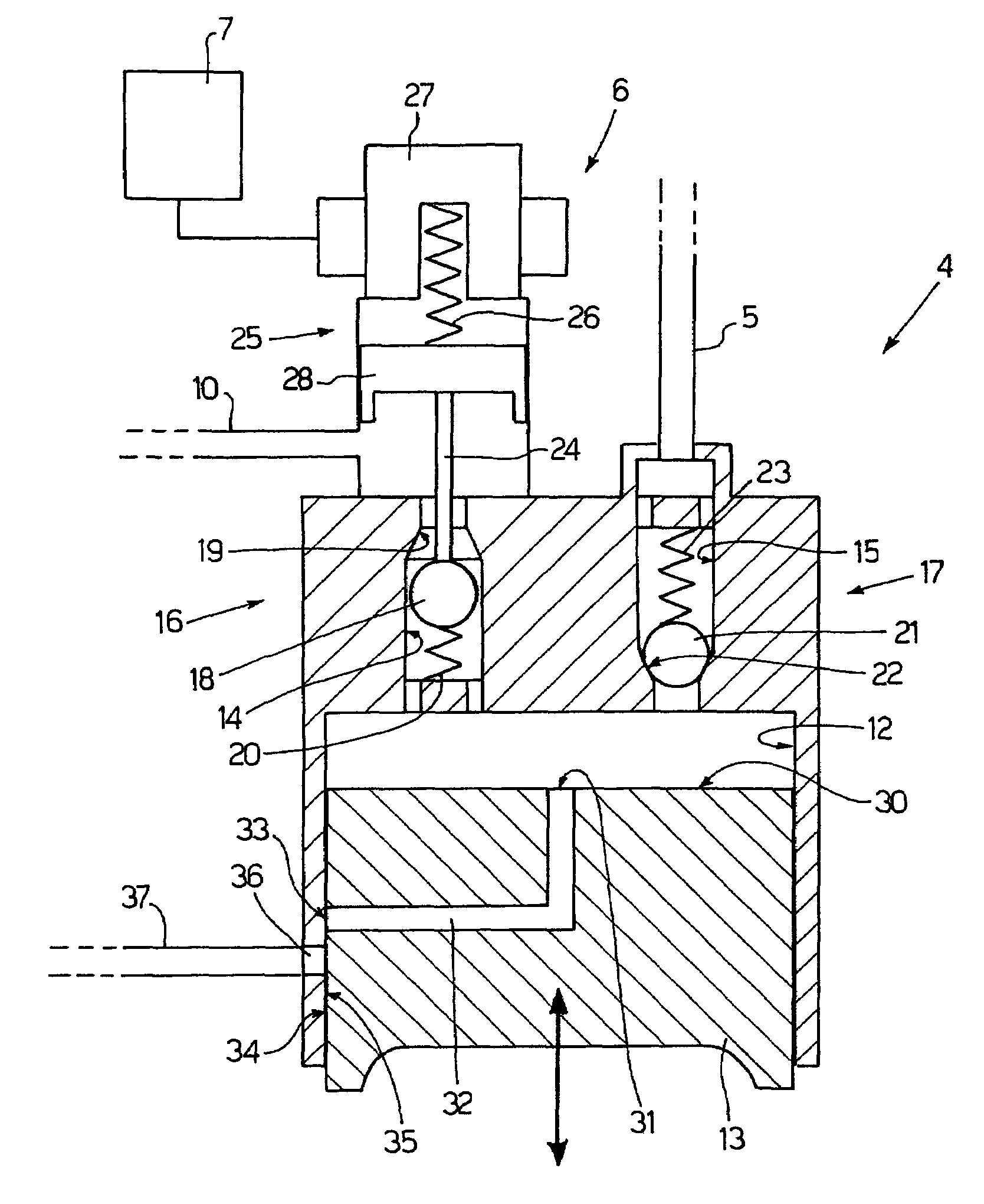
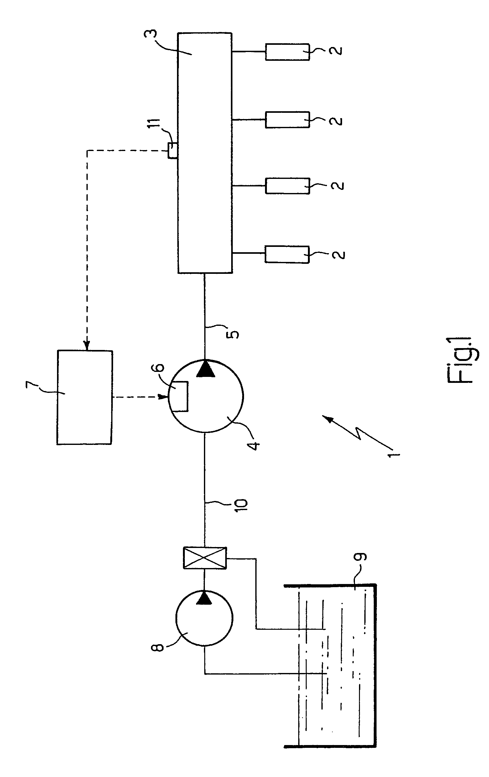
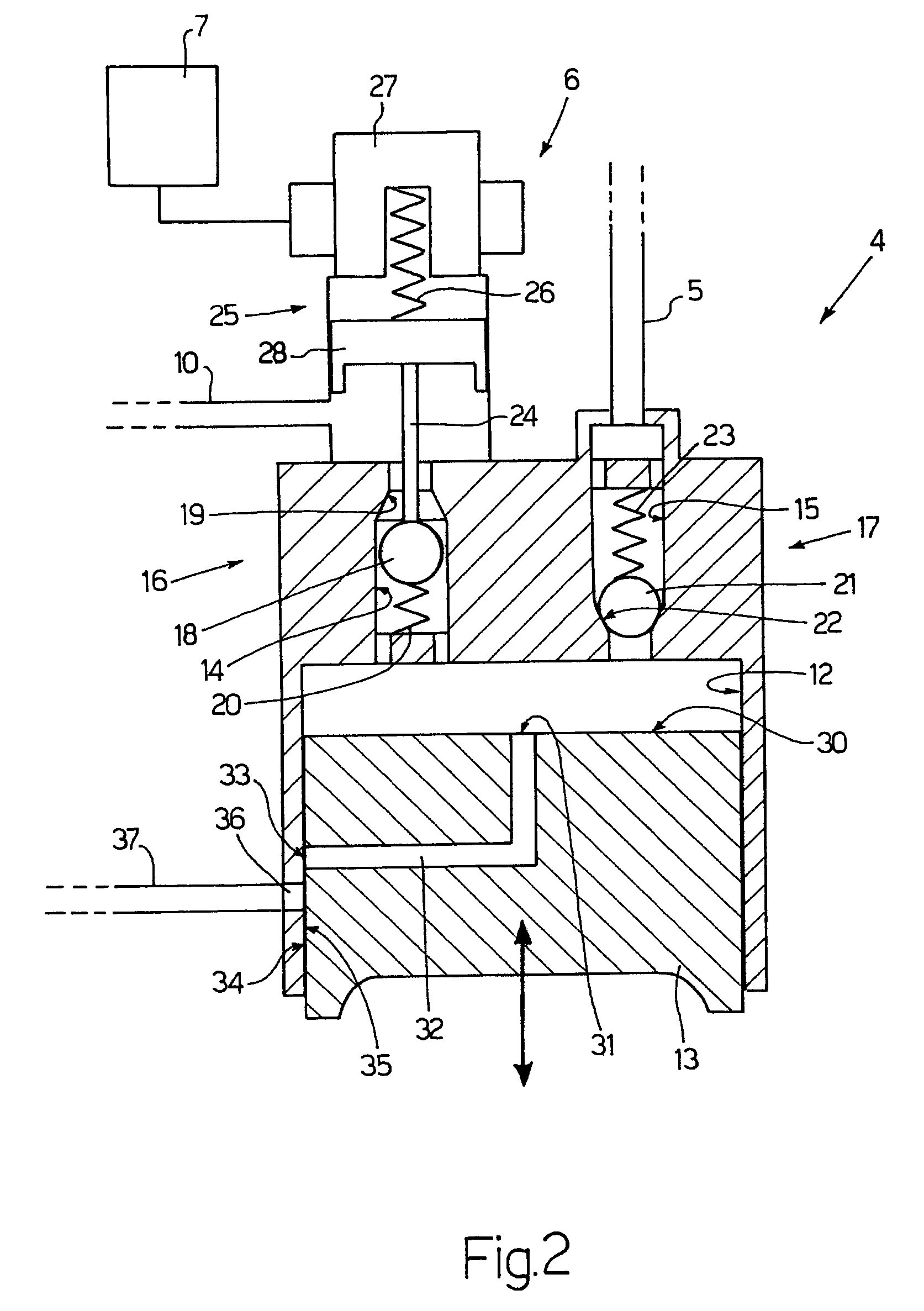
[0023]In FIG. 1, 1 denotes an overall common-rail type system for the direct injection of fuel into an internal combustion engine provided with four cylinders (not shown in detail). The injection system 1 comprises four injectors 2, each of which is capable of injecting fuel directly into the crown of a respective cylinder (not shown in detail) of the engine and receives the pressurised fuel from a common rail 3. A high-pressure pump 4 supplies the fuel to the common rail 3 by means of a tube 5 and is equipped with a device 6 for regulating flow rate driven by a control unit 7 capable of maintaining the fuel pressure within the rail 3 at a desired value, which is generally variable over time as a function of the operating conditions of the engine. A low-pressure pump 8 with a substantially constant flow rate supplies the fuel from a tank 9 to the high-pressure pump 4 by means of a tube 10.

[0024]In general, the control unit 7 regulates the flow rate of the high-pressure pump 4 by mea...


PUM


Abstract

A method and system for the direct injection of fuel into an internal combustion engine, according to which a high-pressure pump with a variable flow rate supplies the fuel to a common rail, which in turn supplies the fuel to a series of injectors; the flow rate of the high-pressure pump is controlled by choking each pump stroke by varying the closure time of an intake valve of said high-pressure pump; for each pump stroke of the high-pressure pump, at least one intermediate gap is generated in said pump stroke during which the pumping pressure is substantially reduced to zero so as to subdivide symmetrically the choking of the pump stroke into a first choking action at the beginning of the pump stroke and a second choking action immediately after the intermediate gap.

Description

CROSS REFERENCE TO RELATED APPLICATION[0001]This application claims priority under 35 U.S.C. § 119 from Italian Patent Application No. BO2004A 000322, filed May 20, 2004. The prior application is incorporated herein by this reference.[0002]The present invention relates to a method and a system for the direct injection of fuel into an internal combustion engine, in particular for direct fuel injection of the common rail type.BACKGROUND OF THE INVENTION[0003]In current common-rail type direct injection systems, a low-pressure pump supplies fuel from a tank to a high-pressure pump, which in turn supplies the fuel to a common rail. A series of injectors (one for each cylinder of the engine) is connected to the common rail, said injectors being driven cyclically in order to inject part of the pressurised fuel present in the common rail into a respective cylinder. If the injection system is to operate correctly, it is important for the fuel pressure level within the common rail constantly...

Claims


Application Information

Patent Timeline
Patent Type & Authority Patents(United States)
IPC IPC(8): F02M37/04F02M37/06F02M59/26F02M59/36F02M63/02
CPCF02M59/265F02M59/366F02M63/0225
Inventor AUSIELLO, FRANCESCOSERRA, GABRIELE
Owner FAB ITAL MAGNETI MARELLI SPA
Why Eureka
Try Eureka