Method for controlling a fuel injector according to a control law which is differentiated as a function of injection time

Inactive Publication Date: 2006-01-03
FAB ITAL MAGNETI MARELLI SPA
View PDF19 Cites 12 Cited by
  • Summary
  • Abstract
  • Description
  • Claims
  • Application Information

AI Technical Summary

Benefits of technology

[0012]The object of the present invention is to provide a method for controlling a fuel injector that does not have the above-descri

Problems solved by technology

Currently available petrol injectors controlled in accordance with the above-described method have a relatively mediocre dynamic range in that, within a critical time interval between opening of the injector and reaching the holding value, the current passing through the injector varies very rapidly and a closure command issued

Method used


Image

  • Method for controlling a fuel injector according to a control law which is differentiated as a function of injection time
  • Method for controlling a fuel injector according to a control law which is differentiated as a function of injection time
  • Method for controlling a fuel injector according to a control law which is differentiated as a function of injection time

Examples


Embodiment Construction

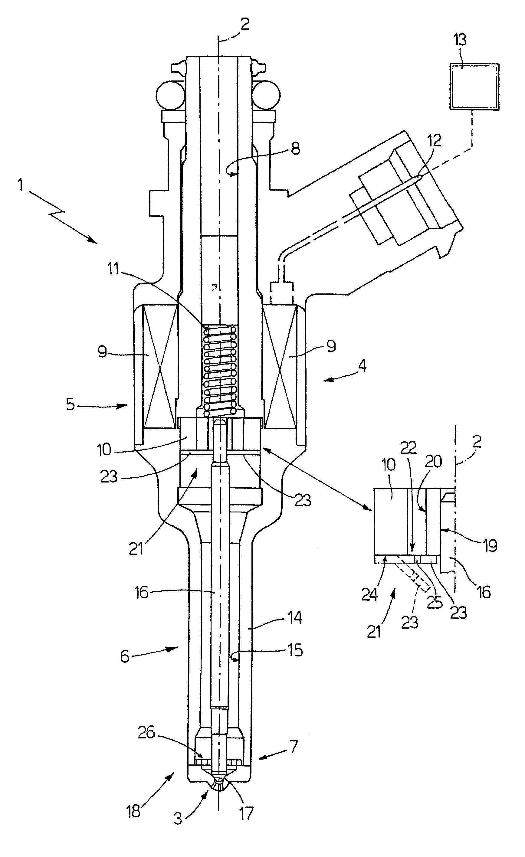
[0022]In FIG. 1 the number 1 denotes the petrol injector as a whole, which is substantially cylindrically symmetrical around a longitudinal axis 2 and is capable of being operated so as to inject petrol from an associated injection nozzle 3. The injector 1 comprises an upper actuator body 4 accommodating an electromagnetic actuator 5, and a lower valve body 6, which is made integral with the actuator body 4 and accommodates a valve 7 actuated by the electromagnetic actuator 5 so as to control the flow of petrol from the injection nozzle 3; the actuator body 4 accommodates the electromagnetic actuator 5 and comprises an internal channel 8, which extends along the entire length of the actuator body 4 in order to supply pressurised petrol to the valve body 6.

[0023]The electromagnetic actuator 5 comprises an electromagnet 9, which is provided with a 36-turn winding having a resistance of approx. 0.12 Ohm, is integral with the actuator body 4 and is capable of displacing along the axis 2...


PUM


Abstract

A method for controlling a fuel injector provided with an electrically operated electomagnetic actuator in such a manner as to open the injector for a determined injection time; the method providing that the injector be operated with a first current waveform if the injection time is greater than a predetermined threshold value, and that the injector be operated with a second current waveform if the injection time is less than the predetermined threshold value; both the current waveforms have an identical initial portion, during which the current passing through the injector is caused to rise until it reaches a peak value, which is maintained by cyclic switching of the voltage applied to the injector between two different values.

Description

[0001]The present invention relates to a method for controlling a fuel injector.[0002]The present invention is advantageously applied to controlling an electromagnetic injector in a direct petrol injection system, to which the following description will make explicit reference without consequently restricting the general scope thereof.BACKGROUND OF THE INVENTION[0003]It is known that an ideal injection system is perfectly linear, i.e. the flow rate at which the petrol is injected (given an identical pressure difference across the injector) is directly proportional to the injection time; thus, for an ideal injection system, the characteristic curve for injection time / flow rate of injected petrol is a straight line. A real injection system differs from the ideal injection system in that it tends to have zones of non-linear operation, i.e. zones of operation in which the characteristic curve for injection time / flow rate of injected petrol deviates from the ideal straight line; in parti...

Claims


Application Information

Patent Timeline
IPC IPC(8): F02M51/00F02B75/12F02D41/20F02D41/34F02D41/38F02M51/06F02M51/08F02M61/12F02M61/16F02M61/18F02M63/00
CPCF02D41/34F02M51/0614F02M51/0671F02M61/12F02M61/162F02M61/18F02D41/20F02B2075/125Y02T10/123F02D41/3809F02D2041/2003F02D2041/2034F02D2041/2044F02D2041/2051F02D2041/2058F02M2051/08F02M2200/30F02M2200/304Y02T10/44F02M51/08Y02T10/12Y02T10/40
Inventor PETRONE, MICHELEMANCINI, LUCAMATTIOLI, MASSIMO
Owner FAB ITAL MAGNETI MARELLI SPA
Why Eureka
Try Eureka