
Horizontal stacking column

Inactive Publication Date: 2006-07-04
MTS MASCHENBAU GMBH
View PDF13 Cites 10 Cited by
  • Summary
  • Abstract
  • Description
  • Claims
  • Application Information

AI Technical Summary

Benefits of technology

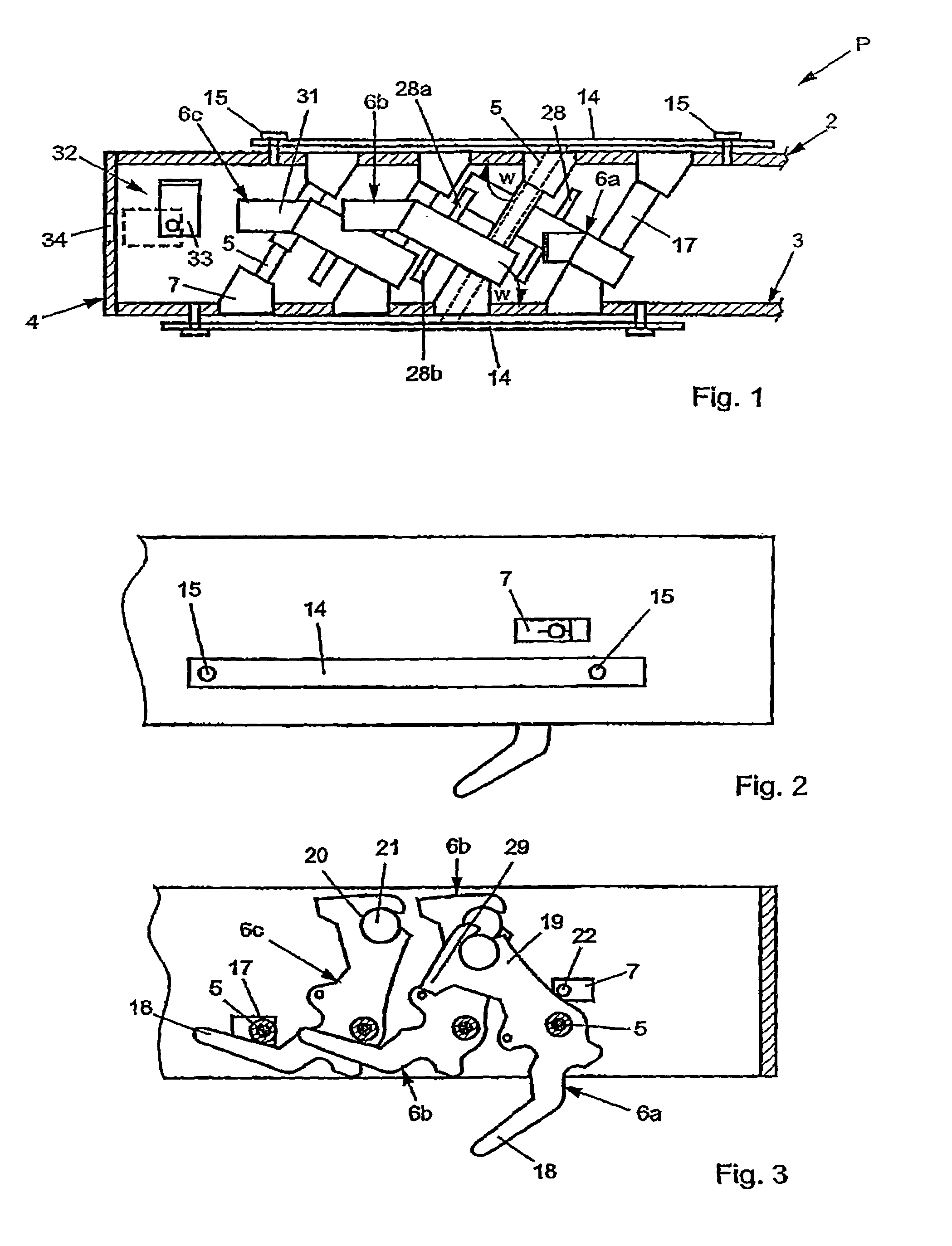
[0010]The significant advantage of the present invention is that the ratchet levers drop back automatically into their rest position again. The control arm preferably has a higher weight than the carrying arm. For this purpose, the control arm itself may additionally be provided with a higher weight, in particular if the ratchet lever is one made of plastic or aluminum. In this case, the control arm may be provided with a higher-weight metal element. The sloping arrangement of the ratchet lever ensures that the latter drops back into its rest position again once the article has been removed. It is merely in the case of the first ratchet lever that this is avoided by a stop pin, with the result that the first ratchet lever is always kept in the standby position.
[0011]The way in which the individual ratchet levers interact in order that, when one ratchet lever pivots into the operating position, the following ratchet lever always passes into the standby position is not important in the present case. The prior art discloses many different possibilities for this, and these are to be covered by the present invention.
[0012]In addition, the present invention also provides a sensor for detecting the loading state of the stacking column. At the moment when the last ratchet lever pivots into the operating position, this is determined by a sensor. For example, in this case, this may be a straightforward hole which is located in an end surface of the stacking column and is closed or obscured by an angle element actuated by the last ratchet lever or by the latter itself. This is then detected by an optical or mechanical sensor.

Problems solved by technology

The horizontal stacking column which has just been described is not suitable for this case.

Method used


Image

  • Horizontal stacking column
  • Horizontal stacking column
  • Horizontal stacking column

Examples


Embodiment Construction

[0020]According to FIG. 1, two wall strips 2 and 3 are arranged parallel and horizontally one above the other and are connected to one another on the end sides by end walls 4. The wall strips 2 and 3 have rotary spindles 5 passing through them at certain intervals, the rotary spindles enclosing acute angles w with the wall strips 2 and 3. The rotary spindles 5 are thus positioned in a sloping manner.

[0021]Only four rotary spindles 5 are shown in the present exemplary embodiment, it being possible to increase the number of rotary spindles 5 as desired, and this number being dependent on the length of the wall strips 2 and 3.

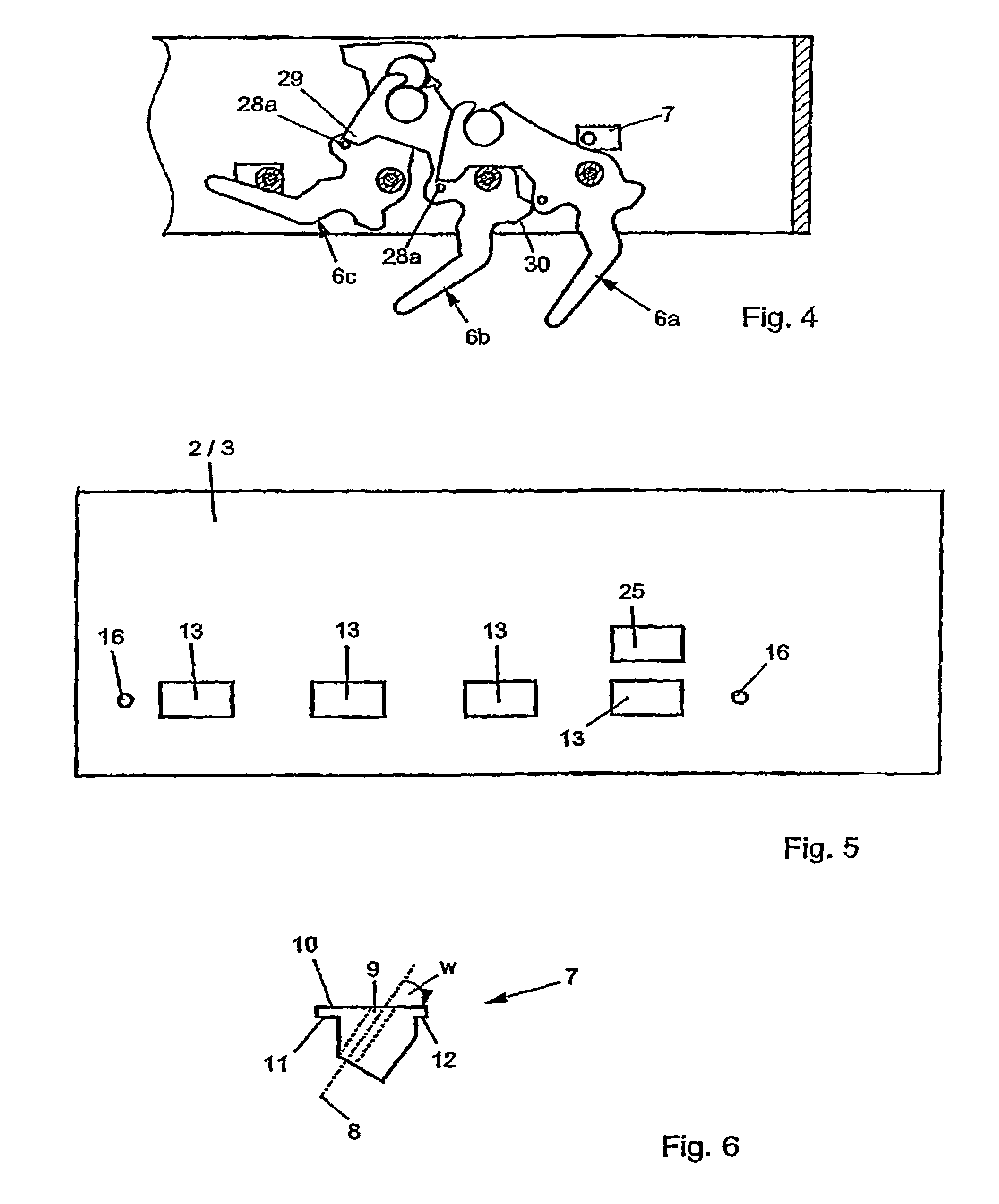
[0022]Each rotary spindle 5 retains a ratchet lever 6, three ratchet levers 6a, 6b and 6c being illustrated in the present exemplary embodiment. The ratchet levers serve for securing an article (not shown specifically).

[0023]For the purpose of fastening the rotary spindles 5, use is made of fastening elements 7, as are shown in particular in FIG. 6. Each fastening...


PUM


Abstract

A horizontal stacking column used to store articles which are placed next to each other at a reciprocal distance on two-armed rachet levers which are rotationally mounted on two axes of rotation between two wall strips, comprising a carrier arm for holding the article to be stored in addition to a control arm. The axes of rotation form an acute angle (w) with the wall strips.

Description

BACKGROUND OF THE INVENTION[0001]The present invention relates to a horizontal stacking column for storing articles one beside the other, at intervals from one another, on two-armed ratchet levers, which are mounted such that they can be rotated on rotary spindles arranged between two wall strips and have, on the one hand, a carrying arm, for retaining the article and, on the other hand, a control arm.[0002]Such stacking columns serve, in particular, for accommodating sheet-like articles, for example for the production of vehicle parts. However, there is also a large number of other application areas which are to be covered by the present invention.[0003]The stacking columns are usually oriented vertically, as are those which are disclosed, for example, in DE 38 11 310.[0004]The prior art also discloses sloping stacking columns, for example in EP 0 536 571. In this case, two wall strips are connected at an acute angle to a base surface, base plate or the like. The ratchet levers are...

Claims


Application Information

Patent Timeline
IPC IPC(8): A47F5/08B65G1/14
CPCB65G1/14
Inventor STROBEL, GUSTAV
Owner MTS MASCHENBAU GMBH
Learn More