Structure for connecting a combination lamp

a technology for connecting structures and lamps, applied in the direction of connecting contacts, penetrating/cutting insulation/cable strands, lighting support devices, etc., can solve the problems of high cost, complex structure, and large so as to reduce the number of component parts and assembling steps, simplify the structure, and ensure the connection. the effect of reliability

Inactive Publication Date: 2006-07-04
YAZAKI CORP
View PDF14 Cites 31 Cited by
  • Summary
  • Abstract
  • Description
  • Claims
  • Application Information

AI Technical Summary

Benefits of technology

[0010]The object of the invention is to provide a structure for connecting a combination lamp which makes it possible to establish reliable electric conn

Problems solved by technology

However, with the above-described conventional lighting apparatus for a vehicle 50, the structure is complex, and the number of component parts and the number of assembling steps become large.
In addition, externally fitting members (winding tap

Method used


Image

  • Structure for connecting a combination lamp
  • Structure for connecting a combination lamp
  • Structure for connecting a combination lamp

Examples


Embodiment Construction

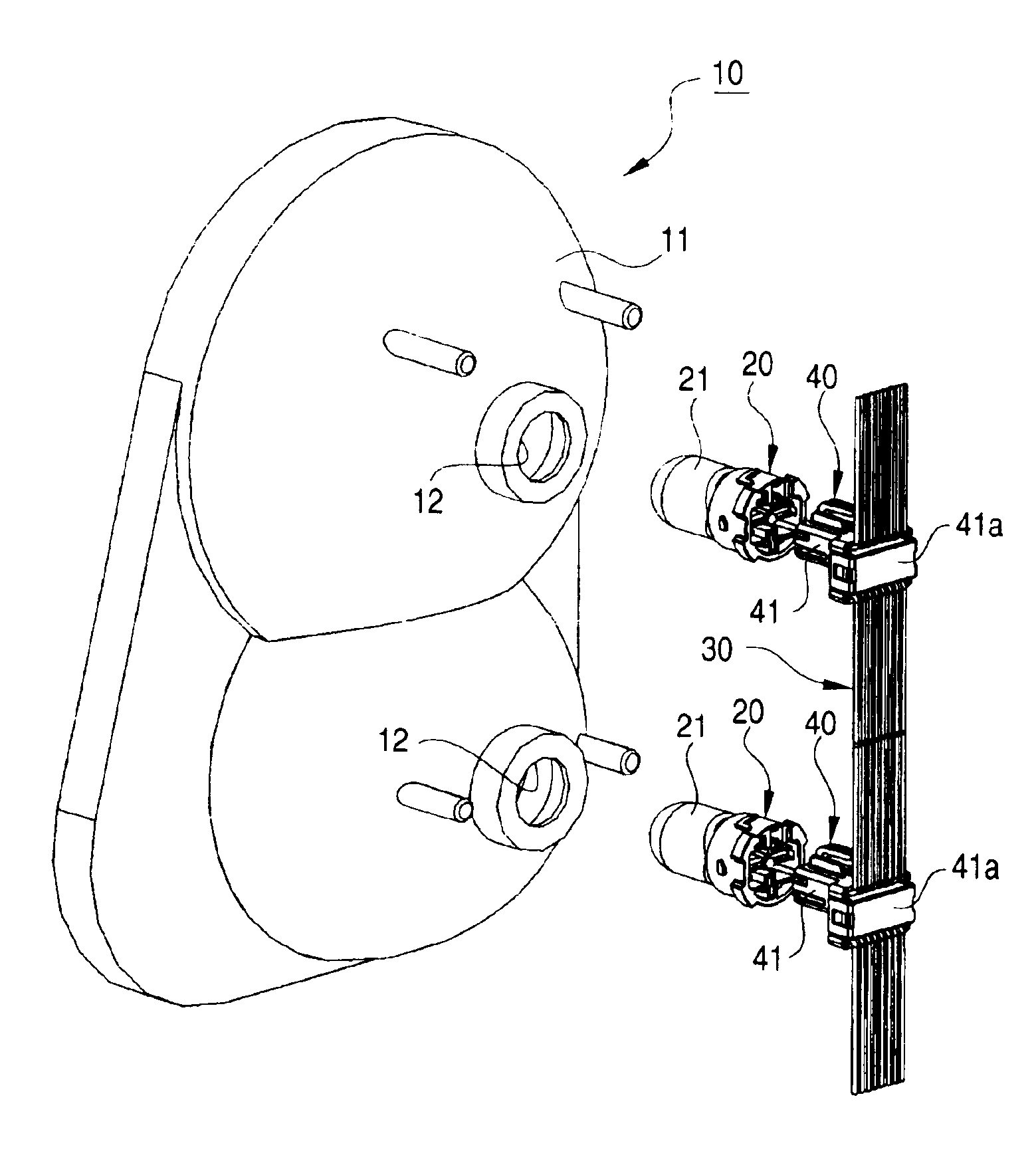
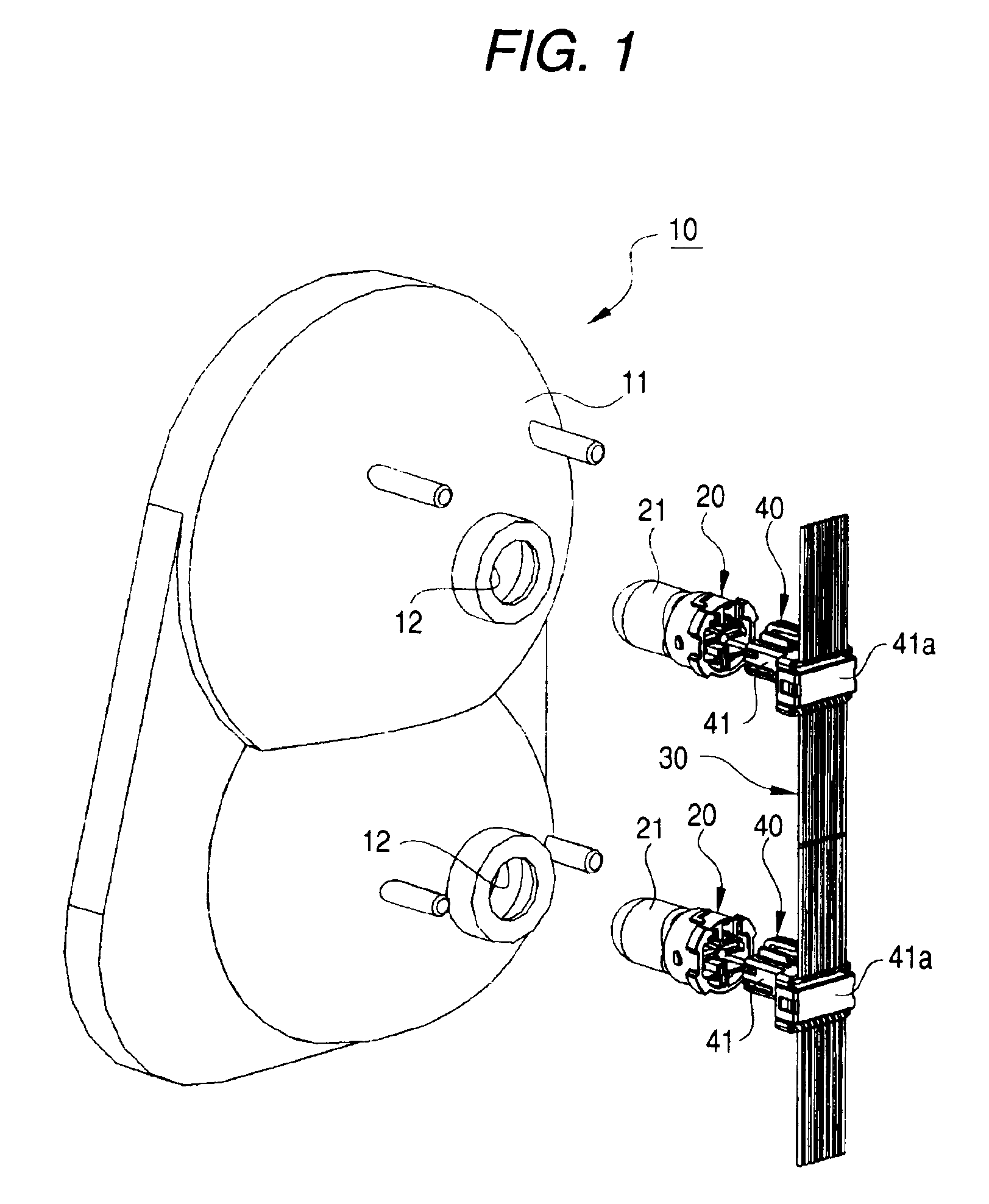
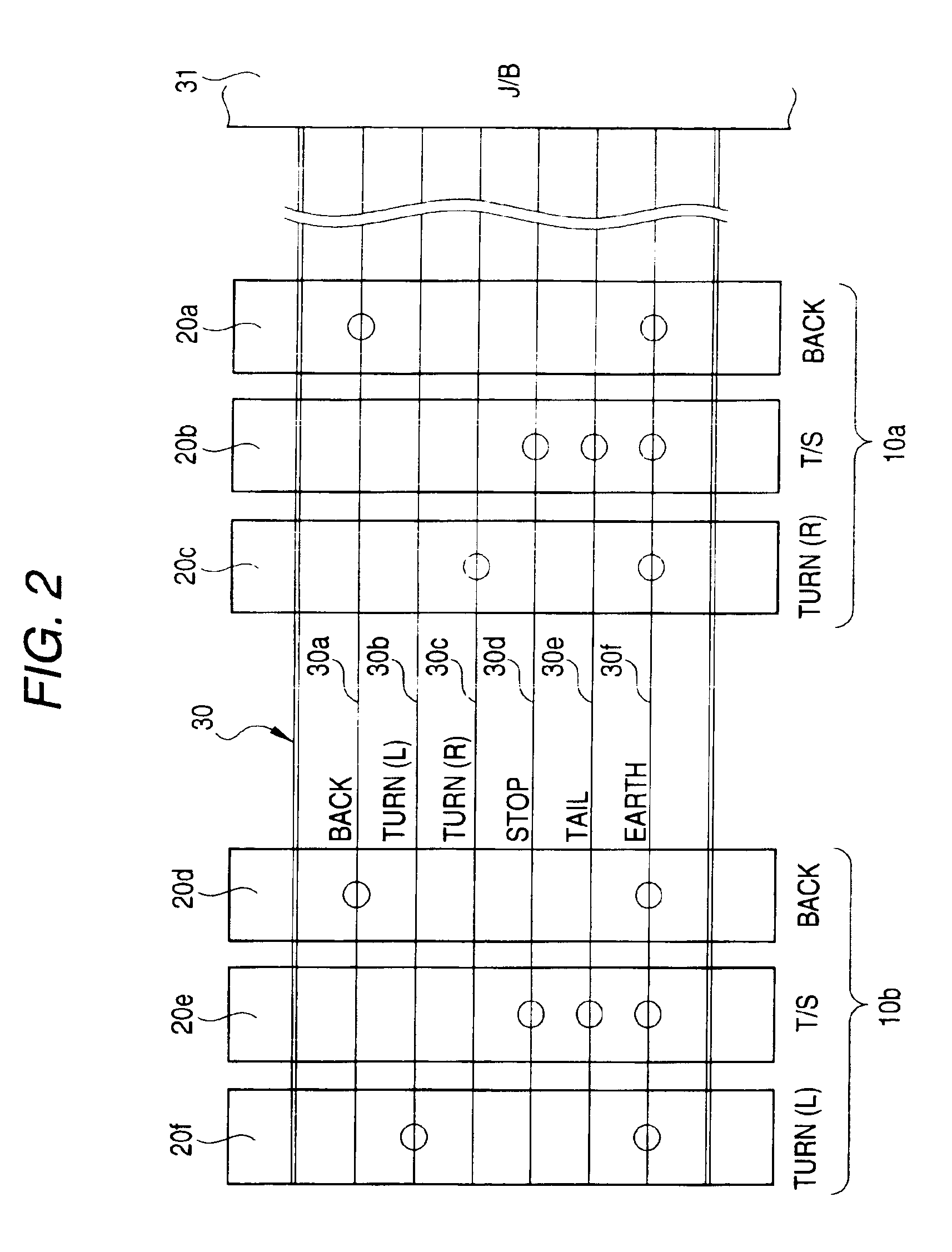
[0040]Referring now to FIGS. 1 to 10, a description will be given of an embodiment of the structure for connecting a combination lamp. FIG. 1 is an exploded perspective view illustrating the structure for connecting a rear combination lamp in accordance with this embodiment. FIG. 2 is a schematic diagram illustrating the state of insulation displacement connection of a flat cable in FIG. 1.

[0041]FIG. 3 is an exploded perspective view illustrating the details of a bulb socket in FIG. 1, and FIG. 4 is a perspective view illustrating a state in which an insulation displacement connector in FIG. 3 is fitted to the flat cable.

[0042]FIG. 5 is a perspective view illustrating the flat cable, the insulation displacement connector, and a socket connector in FIG. 4. FIG. 6 is a perspective view illustrating an interim state in which the socket connector is being engaged with the insulation displacement connector. FIG. 7 is a perspective view illustrating a state in which the engagement of the ...


PUM


Abstract

An insulation displacement connector (40) selectively effects insulation displacement of required conductive paths of a flat cable (30) in correspondence with the function of a bulb socket connector (20). Further, the other unnecessary conductive paths are passed through without being subjected to insulation displacement connection. In addition, as the insulation displacement connector (40) and a socket housing with a bulb (21) fitted thereto are engaged, insulation displacement terminals and bulb conductor portions of the bulb (21) are electrically connected directly.

Description

BACKGROUND OF THE INVENTION[0001]The present invention relates to a structure for connecting a combination lamp for connecting the combination lamp to a wire harness, and more particularly to a connecting structure which is low cost, simple, and reliable.[0002]Conventionally, as shown in FIG. 11, JP-A-10-31906 discloses a lighting apparatus for a vehicle 50 in which a bulb socket 51 integrally having a connector housing constitutes a power feeding socket by connecting a vehicle body-side cable 60 thereto, and in which the bulb socket 51 is connected in a distributive manner to other bulb sockets 54 via splicers 52 and cables (single-core cables) 53. Each of the bulb sockets 51 and 54 holds a bulb 57 in a socket attaching hole 56 provided in a rear surface of a lighting apparatus body 55.[0003]In the above-described lighting apparatus for a vehicle 50, the connector joining portions are concentrated at one location by using the cables 53. Namely, a wire harness-side connector 61 at a...

Claims


Application Information

Patent Timeline
IPC IPC(8): H01R4/24B60R16/02B60Q1/00H01R4/26F21V19/00F21V21/002F21V23/06H01R13/639H01R33/09
CPCF21S48/212H01R12/675F21V21/002H01R33/09F21S43/195H01R9/031
Inventor TASHIRO, HARUNORIFUKUDA, MASARU
Owner YAZAKI CORP
Why Eureka
Try Eureka