
Connector and manufacturing method of the same

Inactive Publication Date: 2006-07-04
AUTONETWORKS TECH LTD +2
View PDF9 Cites 27 Cited by
  • Summary
  • Abstract
  • Description
  • Claims
  • Application Information

AI Technical Summary

Benefits of technology

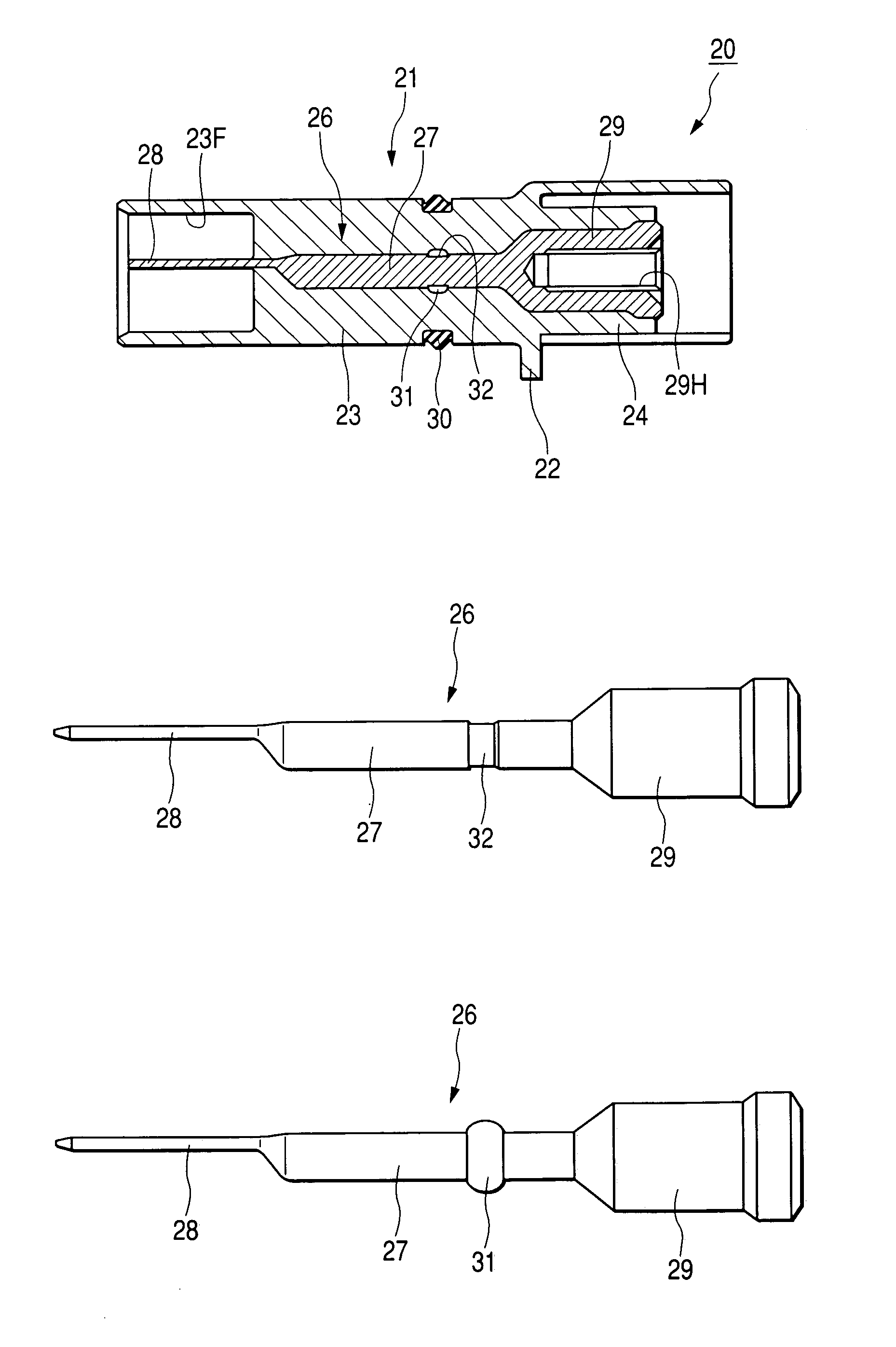
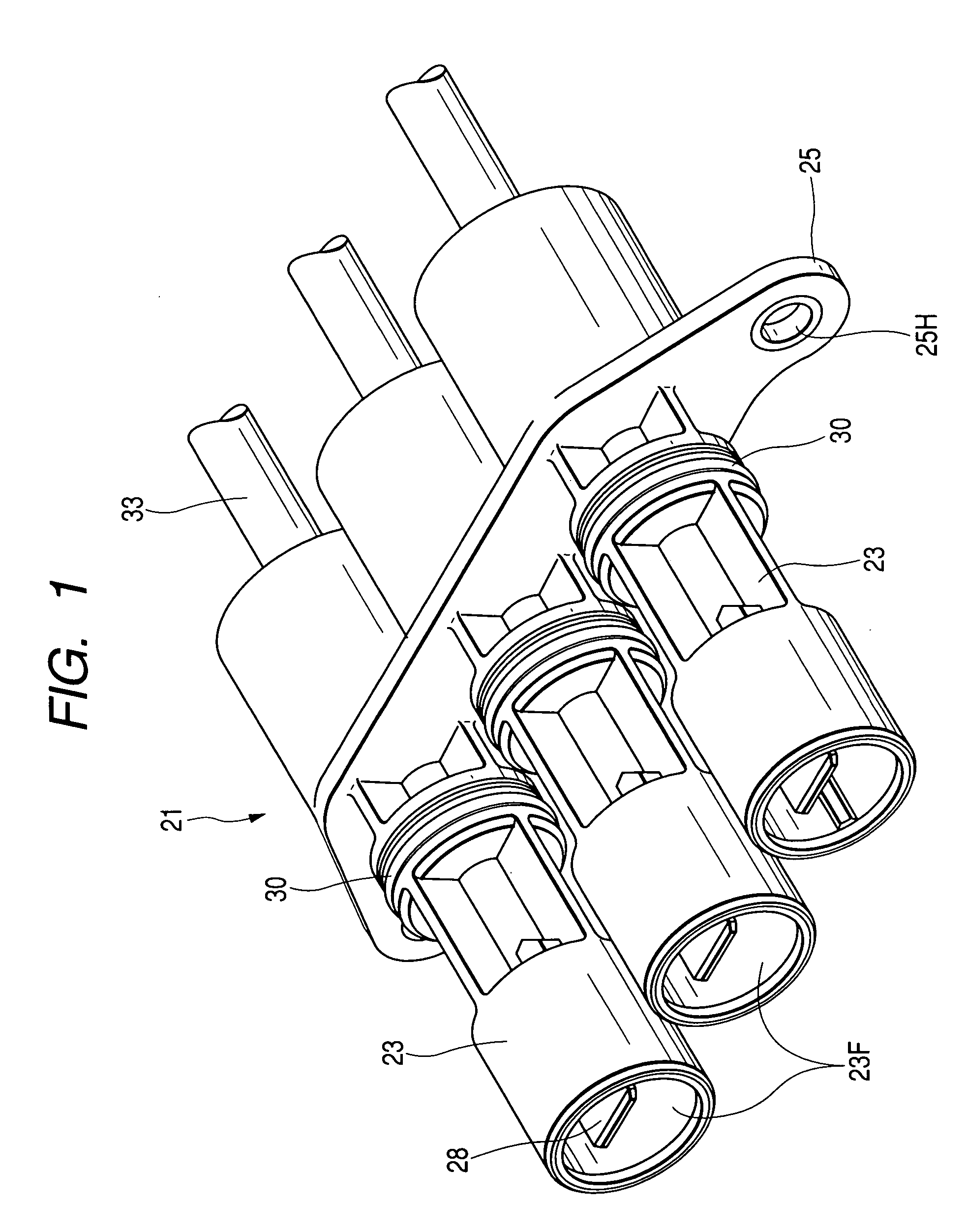
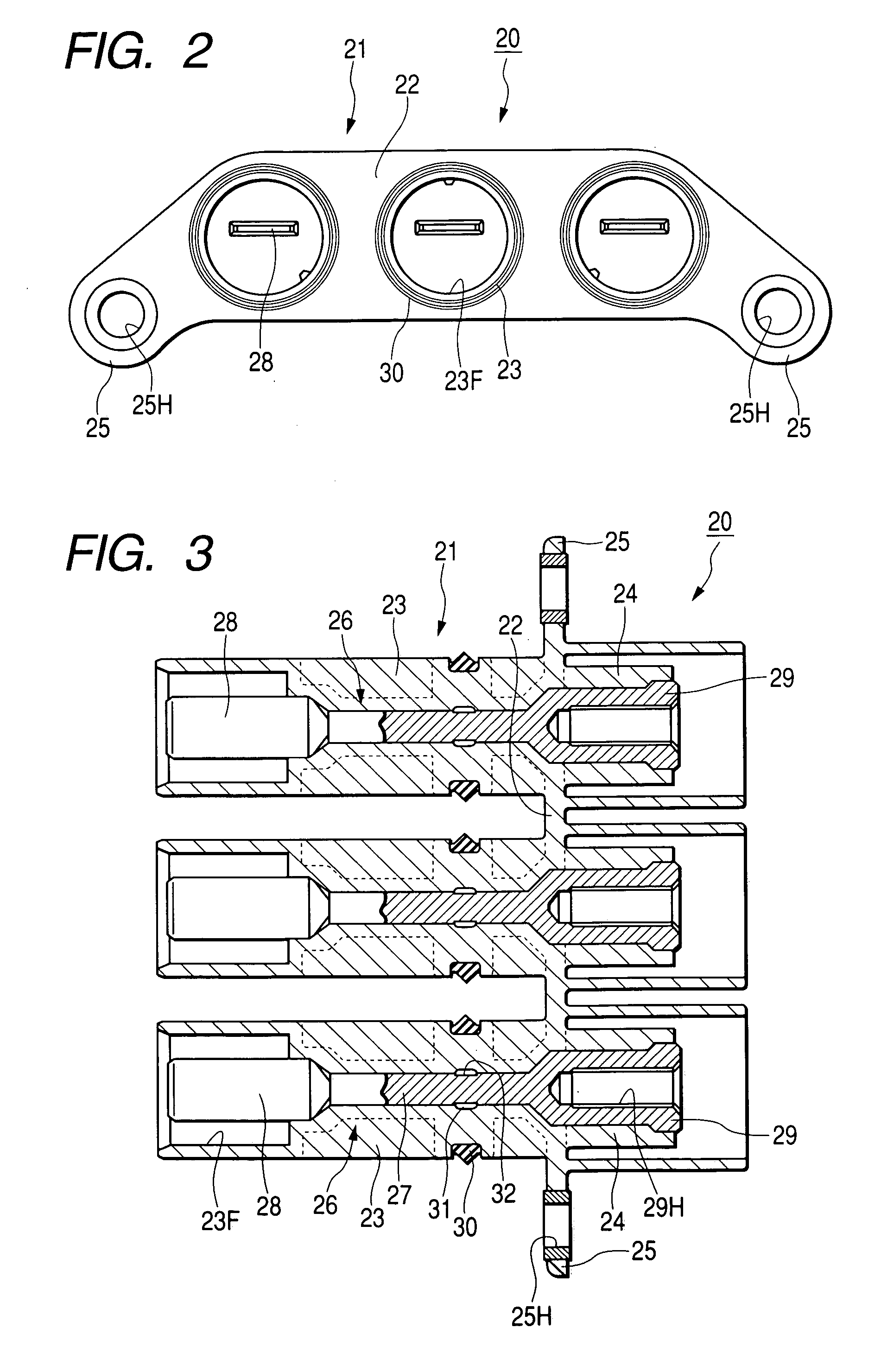
[0007]The present invention has been achieved in the light of the above-mentioned problems, and it is an object of the invention to provide a connector that is buried into a housing having a terminal fitting molded of resin, whereby the sealing performance is stabilized.
[0012]Since the seal member made of rubber is bonded by baking on the outer circumferential face of the terminal fitting as the seal means, it is possible to securely seal a gap between the terminal fitting and the housing because of a resiliency of the seal member without managing the coating amount of sealant which is required when the sealant is coated.

Problems solved by technology

However, the housing simply molded of resin may contain some gaps in a contact portion between the terminal fitting and the housing, or a contact portion between the wire covering and the housing, due to low adhesion of materials, whereby it is apprehended that water or oil may enter the housing through the gap.
However, with the above waterproofing method for coating the sealant, it is difficult to manage the amount of coating the sealant, and it is feared that the sealing performance is decreased due to uneven coating.

Method used


Image

  • Connector and manufacturing method of the same
  • Connector and manufacturing method of the same
  • Connector and manufacturing method of the same

Examples


embodiment 1

[0024]Referring to FIGS. 1 to 9, an embodiment 1 of the present invention will be described below.

[0025]An apparatus side connector 20 (a connector constituting the invention) of this embodiment is provided on an apparatus 10 (e.g., an inverter device for electric automobile) and connected to a wire side connector 50 making up a conductive path A having a shielding function.

[0026]In the apparatus 10, an apparatus main body (not shown) is contained within a conductive shield case 11, and the apparatus side connector 20 connected to the apparatus main body is contained within the same shield case 11. At the upper end part on a side wall of the shield case 11, three circular mounting holes 12, left and right, to penetrate longitudinally are formed at a fixed pitch. On an outside face of the shield case 11, a bulge portion 13 in the form where the open areas of the three mounting holes 12 and their peripheral areas are extended outside is formed. The outer circumference of the bulge por...


PUM


Abstract

A connector of the invention includes a housing including a terminal fitting, which is made by resin molding; and a ring-like seal member made of rubber, which bonded by molding around a circumference of the terminal fitting so that sealing is steadily performed between the terminal fitting and the housing. It is not necessary to adjust an amount of sealing material applied to the terminal fitting in case that the sealing material is applied to the terminal fitting.

Description

BACKGROUND OF THE INVENTION[0001]1. Field of the Invention[0002]The present invention relates to a connector that is buried into a housing having a terminal fitting molded of resin.[0003]2. Description of the Related Art[0004]There is a connector of this kind in which a housing is molded of resin in such a manner that a terminal fitting is connected to a wire terminal, and a connecting portion between the terminal fitting and the wire is buried therein. This connector is employed in the environments where water-resistance is required. However, the housing simply molded of resin may contain some gaps in a contact portion between the terminal fitting and the housing, or a contact portion between the wire covering and the housing, due to low adhesion of materials, whereby it is apprehended that water or oil may enter the housing through the gap.[0005]Thus, conventionally, there was a method in which a sealant is thinly coated on the outer circumferential face of the terminal fitting or...

Claims


Application Information

Patent Timeline
IPC IPC(8): H01R13/40H01R43/00H01R9/03H01R13/52
CPCH01R9/032H01R13/5221H01R13/521H01R13/65912
Inventor MIYAZAKI, SHO
Owner AUTONETWORKS TECH LTD
Learn More