

Identifying defective data sectors in a disk drive
- Summary
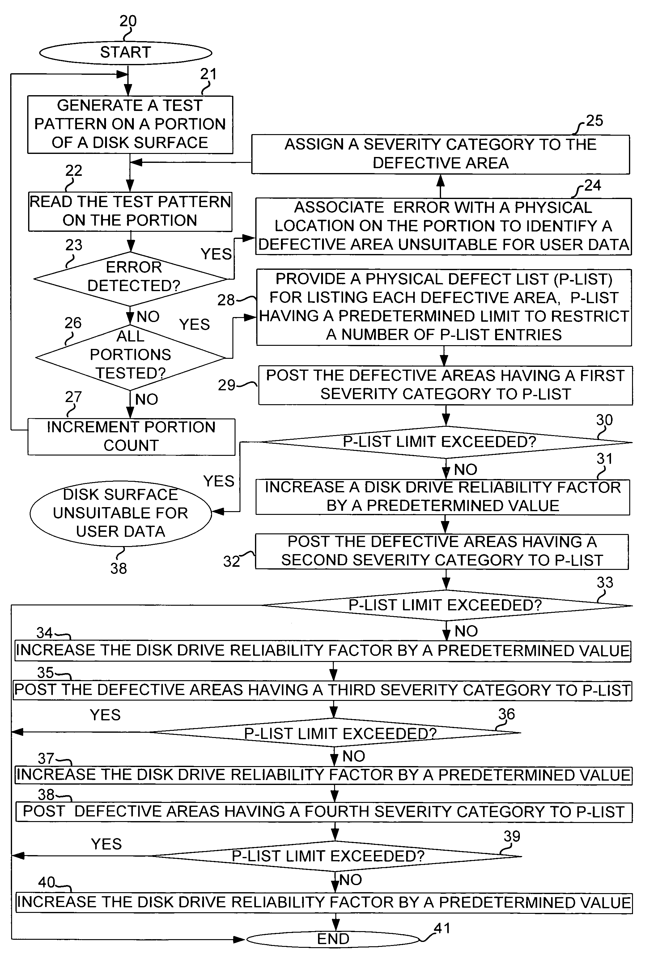
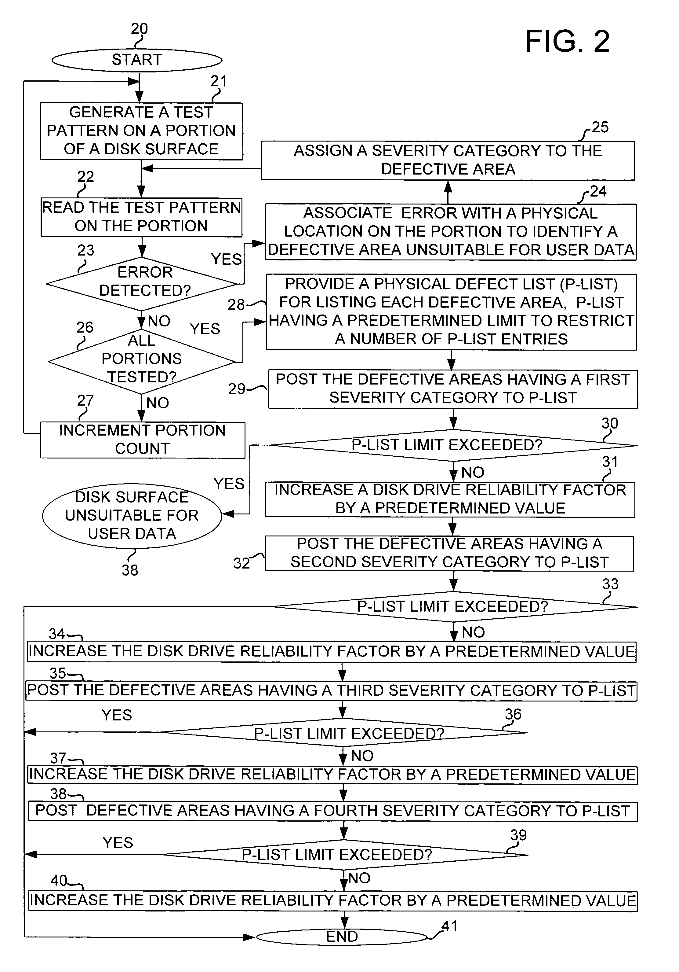
- Abstract
- Description
- Claims
- Application Information
AI Technical Summary
Problems solved by technology
Method used
Image

Examples
Embodiment Construction
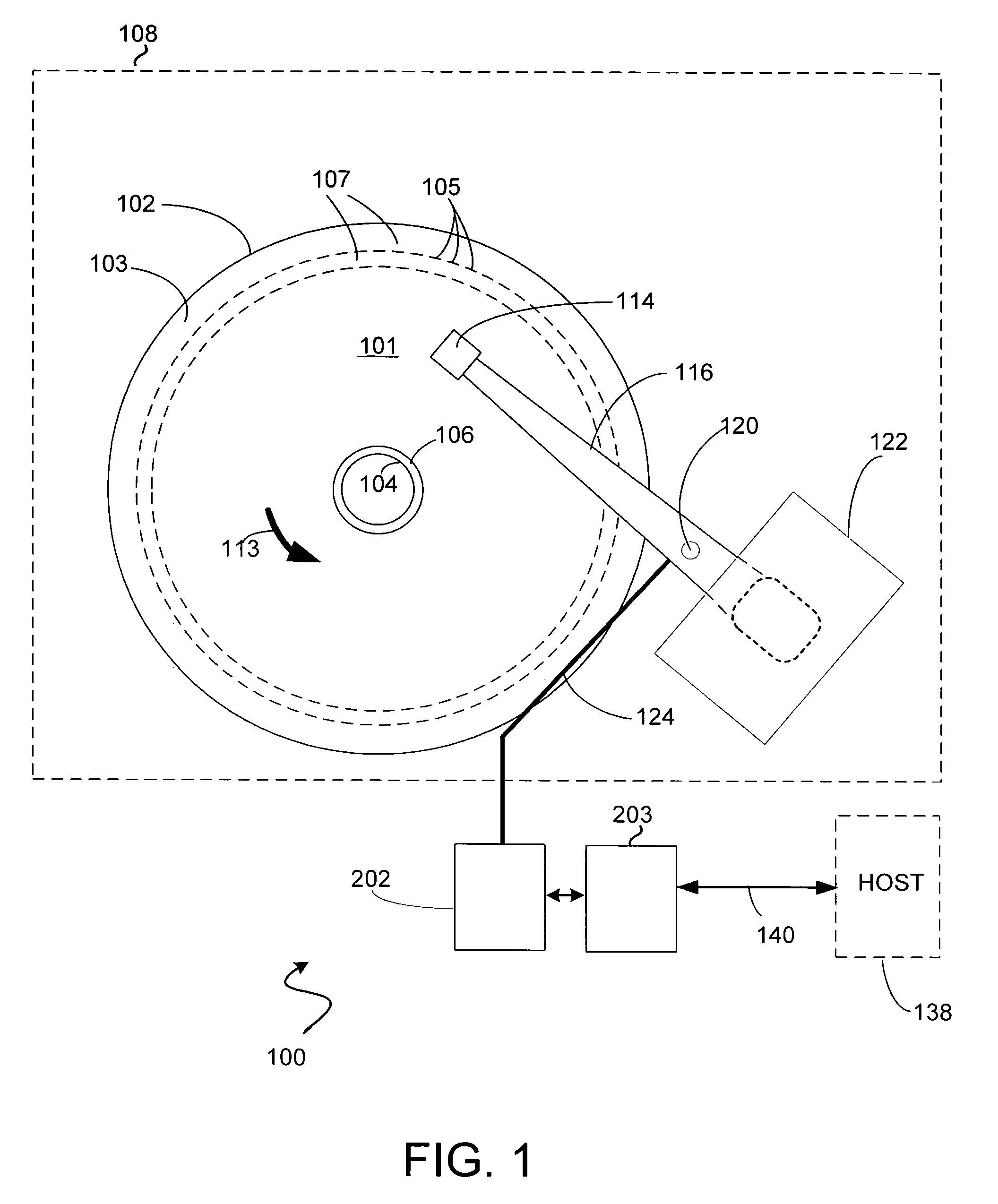
[0010]With reference to FIG. 1, an exemplary hard disk-drive 100 is shown in which the present invention may be practiced. As shown, the hard disk drive 100 includes a head disk assembly (HDA) 108 having one or more disks 102 with a magnetic media 101 having a plurality of tracks 107 each with a plurality of data sectors 105, formed on each surface 103 of a disk 102. The HDA 108 further comprises a head 114 mounted on a rotary actuator 116 that rotates about a pivot 120 via controlled torques applied by a voice coil motor (VCM) 122. While the disk drive 100 is in operation, the disk 102 rotates in an exemplary direction 113 about the axis of the spindle 104 at a substantially fixed angular speed such that the surface 103 of the disk 102 moves relative to the head 114.
[0011]As shown in FIG. 1, a signal bus 124, such as a flex cable, interconnects the HDA 108 to a control system 202 which can control the movement of the actuator 116 for moving the actuator 116 to position the head 114...
PUM
 Abstract
Description
Claims
Application Information