
Path search method, channel estimation method and communication device

a path search and channel estimation technology, applied in the field of path search methods, channel estimation methods and communication devices, can solve problems such as reducing path search accuracy

Inactive Publication Date: 2006-07-04
NTT DOCOMO INC
View PDF23 Cites 52 Cited by
  • Summary
  • Abstract
  • Description
  • Claims
  • Application Information

AI Technical Summary

Benefits of technology

[0025]It is a first and more specific object of the present invention to provide a path search method which can be used for RAKE reception and can implement high-accuracy path search irrespective of the continuity of the transmission signal and a communication device using such a path search method.
[0057]It is a further object of the present invention to provide a communication device for implementing channel estimation for estimating channel variation using pilot symbols, the device including: a subcarrier acquiring part for acquiring a plurality of subcarriers included in a received packet; a pilot symbol acquiring part for acquiring a plurality of pilot symbols of known phase included in the plurality of subcarriers, respectively; and a channel estimation part for implementing channel estimation for each of the subcarriers using the plurality of pilot symbols. According to the communication device of the present invention, the above-mentioned second object of the invention can be achieved.

Problems solved by technology

Therefore, as in the case of signal transmission based on packets, in which the signals do not exist continuously but are transmitted intermittently, the above-mentioned path search method may give rise to a problem that an averaging process in a fixed period of time cannot be implemented and thus resulting a reduced path search accuracy.
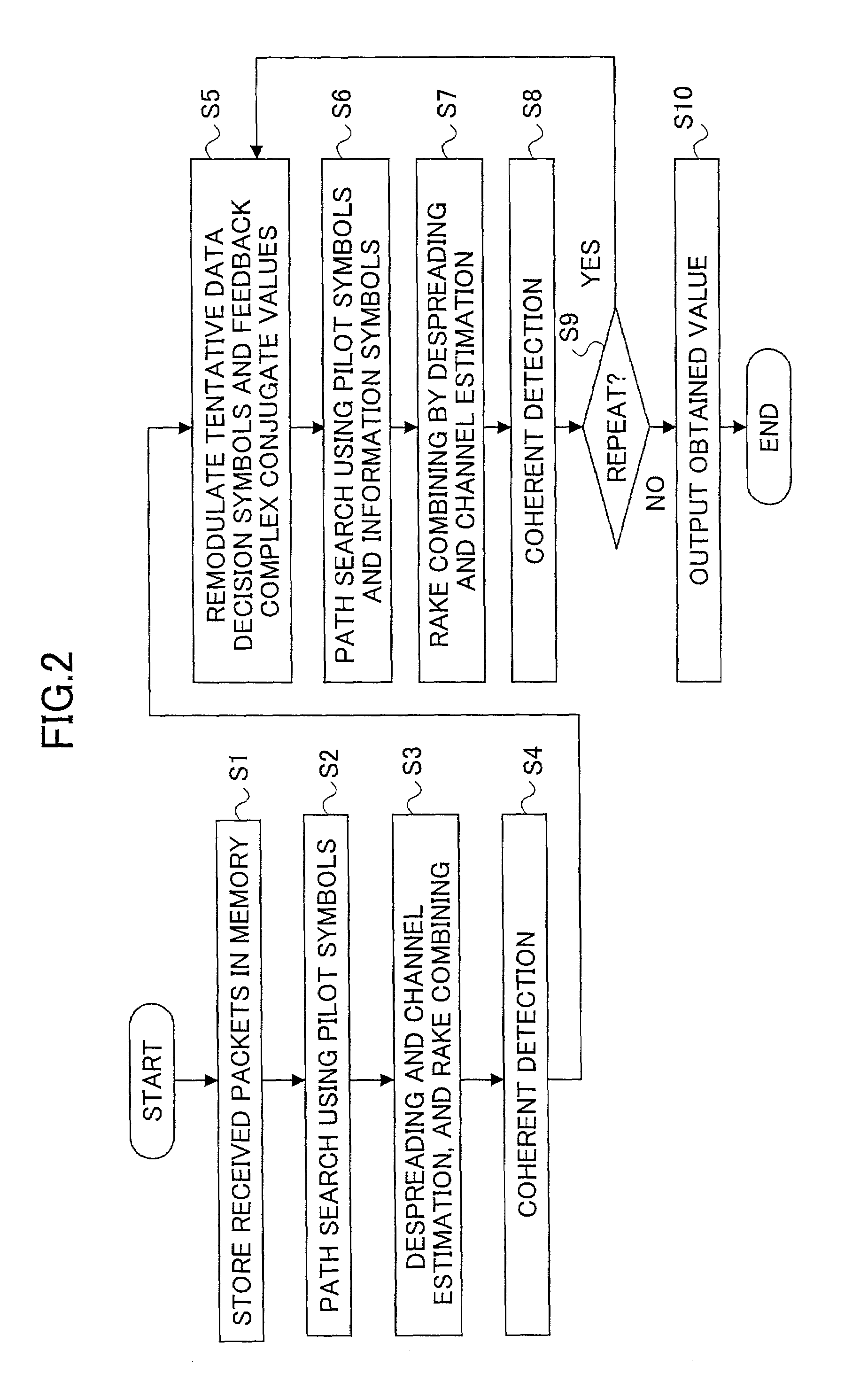
However, in a mobile communication system, since the reliability of the received signal varies due to noise, interference signals, etc., it is not preferable to remodulate the tentative data decision information symbols and feedback all of them.

Method used


Image

  • Path search method, channel estimation method and communication device
  • Path search method, channel estimation method and communication device
  • Path search method, channel estimation method and communication device

Examples


first embodiment

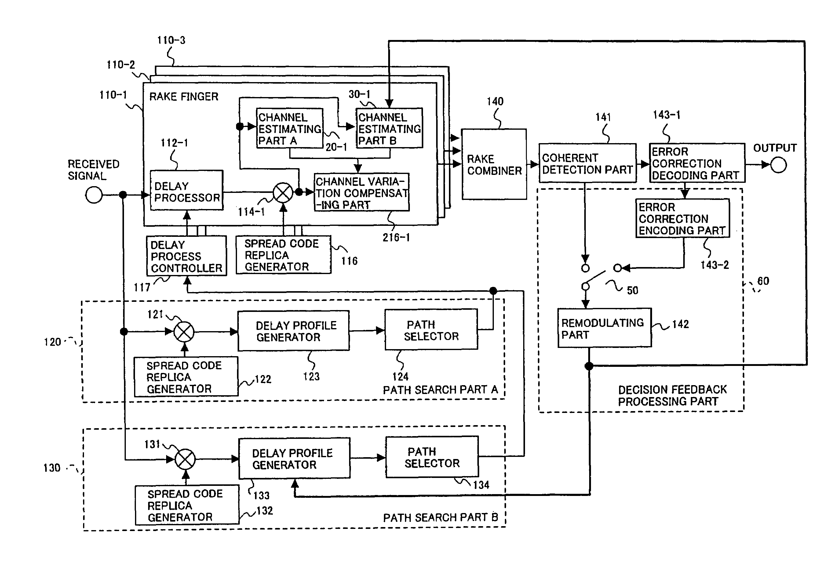
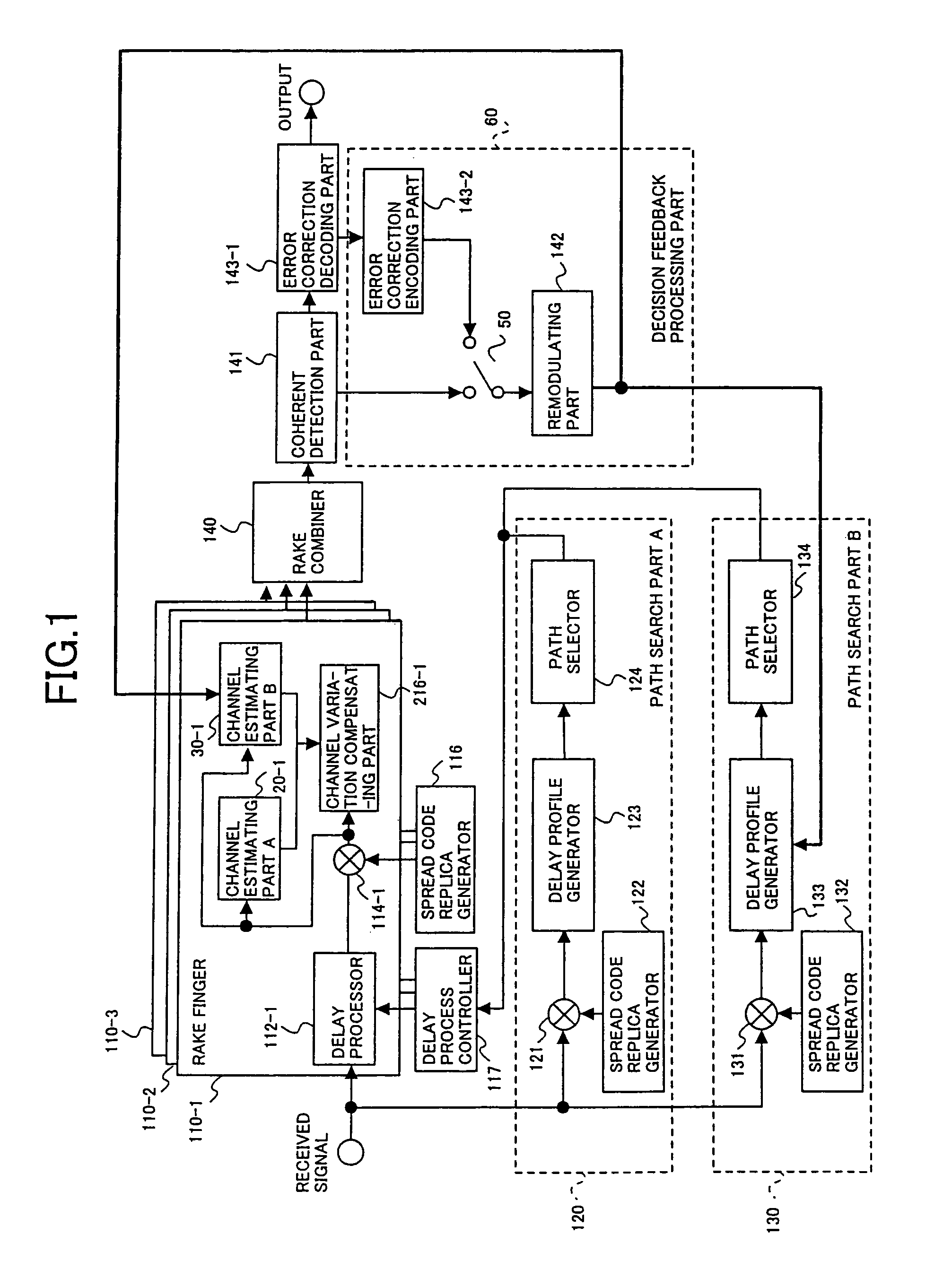
[0093]FIG. 1 is a block diagram showing a general configuration of a communication device of the present invention. A communication device 1 generally includes a path search part A 120, a path search part B 130, a spread code replica generator 116, a delay process controller 117, RAKE finger circuits 110-1 to 110-3, a RAKE combiner 140, a coherent detection part 141, a remodulating part 142, an error correction decoding part 143-1, an error correction encoding part 143-2 and a switch 50, which are connected as shown in the figure. Signals are received through a multipath propagation path via elements such as an antenna, a frequency converter, an analog / digital (A / D) converter and a memory, all of which are not shown, and are input to the path search part A 120, to the path search part B 130 and to the RAKE finger circuits 110-1 to 110-3.

[0094]The path search part A 120 generally includes a multiplier 121 whereto the received signals are supplied, a spread code replica generator 122,...

fourth embodiment

[0146]In the present embodiment, a process similar to a process performed in the path search part is implemented and the information symbols error correction coded again are supplied to the remodulating part 142. The remodulating part 142 remodulates the supplied information symbols and supplies complex conjugate values thereof to a serial-to-parallel converter 216. The serial-to-parallel converter 216 converts the supplied complex conjugate values to a plurality of sequences, and then feeds back the converted complex conjugate values to the delay profile generator 133 of the circuits 200-1 to 200-m, respectively.

[0147]The path search part B 130 despreads the pilot symbols and the information symbols of the supplied signal for each subcarrier. As in the case of the path search part A 120, the despreading processes are implemented in the multipliers 131 included in the circuits 200-1 to 200-m, respectively, such that the pilot symbols and the information symbols of the supplied signa...

tenth embodiment

[0230]Channel estimation may be applied to each sequence of the subcarrier in accordance with the configuration shown in FIG. 27. FIG. 27 is a block diagram showing a configuration of a channel estimation part implemented for each of the subcarrier sequence in the channel estimation part. In FIG. 27, elements similar to those shown in FIG. 22 are indicated with corresponding reference numerals and will not be explained in detail.

[0231]Firstly, the channel variation estimating part A 232 implements channel estimation using pilot symbols. The channel estimation method using the pilot symbols may be a method adopted in either one of the first to fifth embodiments of the channel estimating part described above. Next, the channel variation compensation part 234 compensates for the channel variation by multiplying the complex conjugate values ξA,k,d(i) of the derived channel estimation value by the corresponding information symbols rk,d(i), the coherent detection and tentative data decisi...


PUM


Abstract

A communication device includes at least one of path search means for detecting respective timings of path components included a signal received via a multipath propagation path using pilot symbols of a known phase included in said received signal and channel estimation means for estimating channel variation using the pilot symbols. The path search means includes a first path search part for detecting respective timings of path components using pilot symbols and a second path search part for detecting respective timings of path components using information symbols derived from a signal demodulated according to the timings detected in the first path search part and pilot symbols. The channel estimation means includes a pilot symbol acquiring part for acquiring pilot symbols included in the received signal and a channel estimation part for implementing channel estimation using the acquired pilot symbols.

Description

TECHNICAL FIELD[0001]The present invention relates to a path search method, a channel estimation method and a communication device, and particularly relates to a path search method used for RAKE reception, to a communication device using such a path search method and to a channel estimation method for estimating channel variation and a communication device using such a channel estimation method.BACKGROUND ART[0002]Recently, CDMA (Code Division Multiple Access) system has become one of the mobile communication systems of a greater interest. CDMA system is a communication technology based on Spread Spectrum technology.[0003]Generally, in a mobile communication environment, since a signal transmitted from a transmitter reaches to a receiver via a plurality of propagation paths, i.e., a so-called a multipath propagation path, a received signal is composed of a sum of multipath signals. Therefore, the received signal is composed of signal components having various time-of-arrivals, ampli...

Claims


Application Information

Patent Timeline
Patent Type & Authority Patents(United States)
IPC IPC(8): H04B1/69H04B1/707H04B1/7117H04L5/02H04L25/02H04L27/26H04W28/18H04W76/02
CPCH04B1/7113H04L25/0222H04L25/0226H04L25/0236H04L25/0216H04B1/7077H04B1/7117H04B2201/70701H04L5/0021H04L2025/03414H04L25/03324H04L25/03331H04B1/76
Inventor ATARASHI, HIROYUKIABETA, SADAYUKISAWAHASHI, MAMORU
Owner NTT DOCOMO INC
Learn More