
Method for making X-ray anti-scatter grid

a grid and x-ray technology, applied in the field of medical radiography, can solve the problems of information-containing x-ray radiation, scattered x-ray radiation is particularly serious, aluminum or fiber interspace filler material absorbs some of the primary, and low energy

Inactive Publication Date: 2006-07-04
ANLOGIC CORP (US)
View PDF7 Cites 12 Cited by
  • Summary
  • Abstract
  • Description
  • Claims
  • Application Information

AI Technical Summary

Benefits of technology

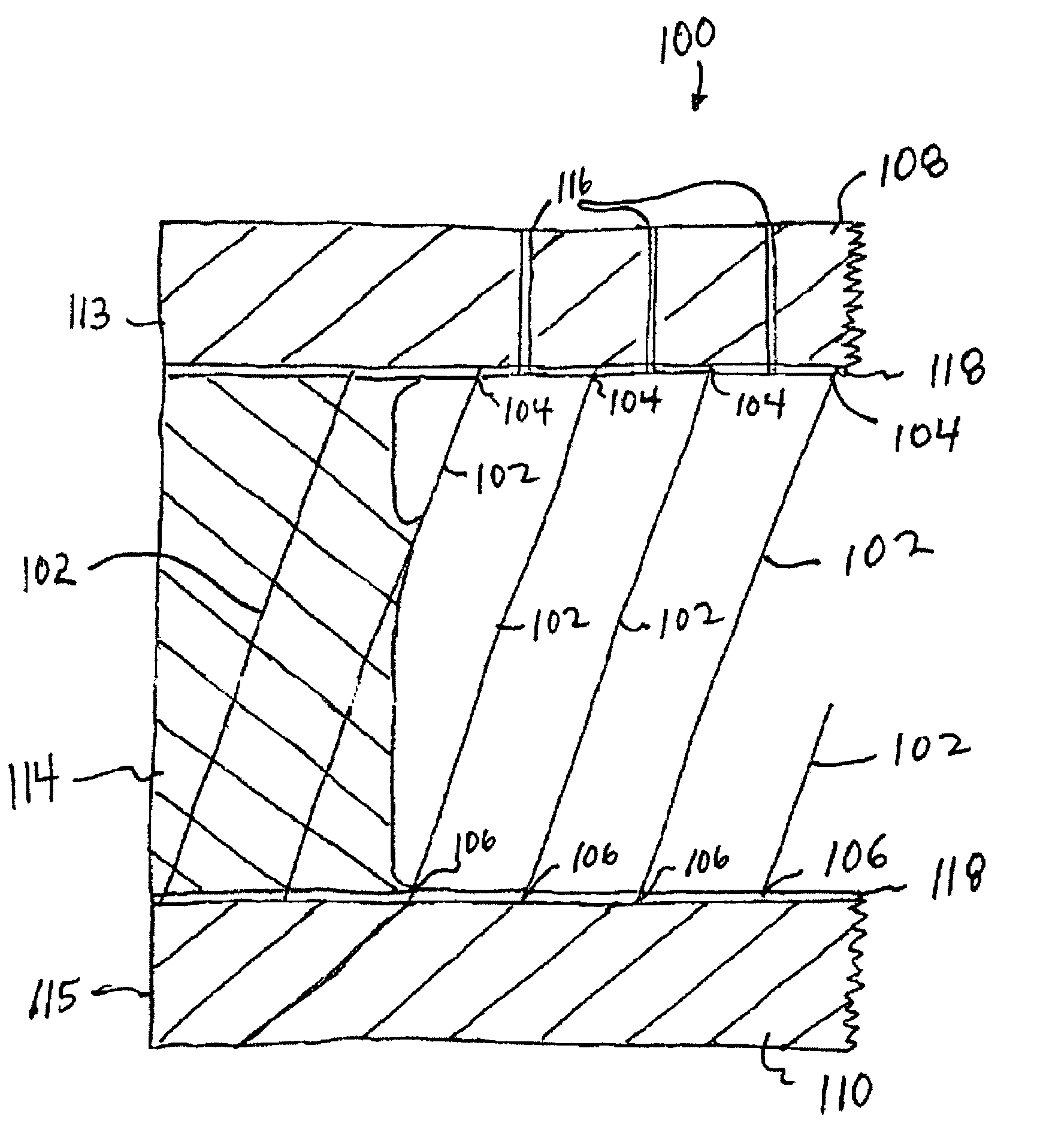
[0011]Exemplary embodiments of the present invention provide a new and improved method for making anti-scatter grids. One exemplary embodiment of a method according to the present invention for manufacturing an anti-scatter grid includes arranging a plurality of elongated metal ribbons of radio-opaque material so that each ribbon is substantially straight and lies in a plane that passes through a focal point of the grid, and placing the elongated ribbons under tension. A first sheet of radiolucent material(also referred to herein as “radioluscent ”material) is secured to top edges of the ribbons, and a second sheet of radioluscent material is secured to bottom edges of the ribbons. The ribbons are arranged such that the first and second radioluscent sheets are substantially parallel. The the tension is removed from the ribbons. The resulting grid is a structural sandwich that is very rigid even though it is made from flexible components.

Problems solved by technology

Scattered X-ray radiation (sometimes referred to as secondary or off-axis radiation) is generally a serious problem in the field of radiography.
Scattered X-ray radiation is a particularly serious problem in the field of X-ray patient diagnostic imaging procedures, such as mammographic procedures, where high contrast images are required to detect subtle changes in patient tissue.
One problem with conventional grids of the type described above is that the aluminum or fiber interspace filler material absorbs some of the primary, relatively low energy, information-containing X-ray radiation.
Another problem with such conventional focused grids of the parallel lamellae type described above is that they do not block scattered radiation components moving in a direction substantially parallel to the plane of the lamellae.
However, the presence of walls at right angles mean that there is no direction which is perpendicular to all the walls, which makes moving the grids much more difficult.
Proper movement of the grid is very critical, but is also difficult, resulting in significant reliability problems.
However, it has been found that the etching method of Pellegrino, et al. does not produce grids with very fine and precise dimensions, as desired.

Method used


Image

  • Method for making X-ray anti-scatter grid
  • Method for making X-ray anti-scatter grid
  • Method for making X-ray anti-scatter grid

Examples


Embodiment Construction

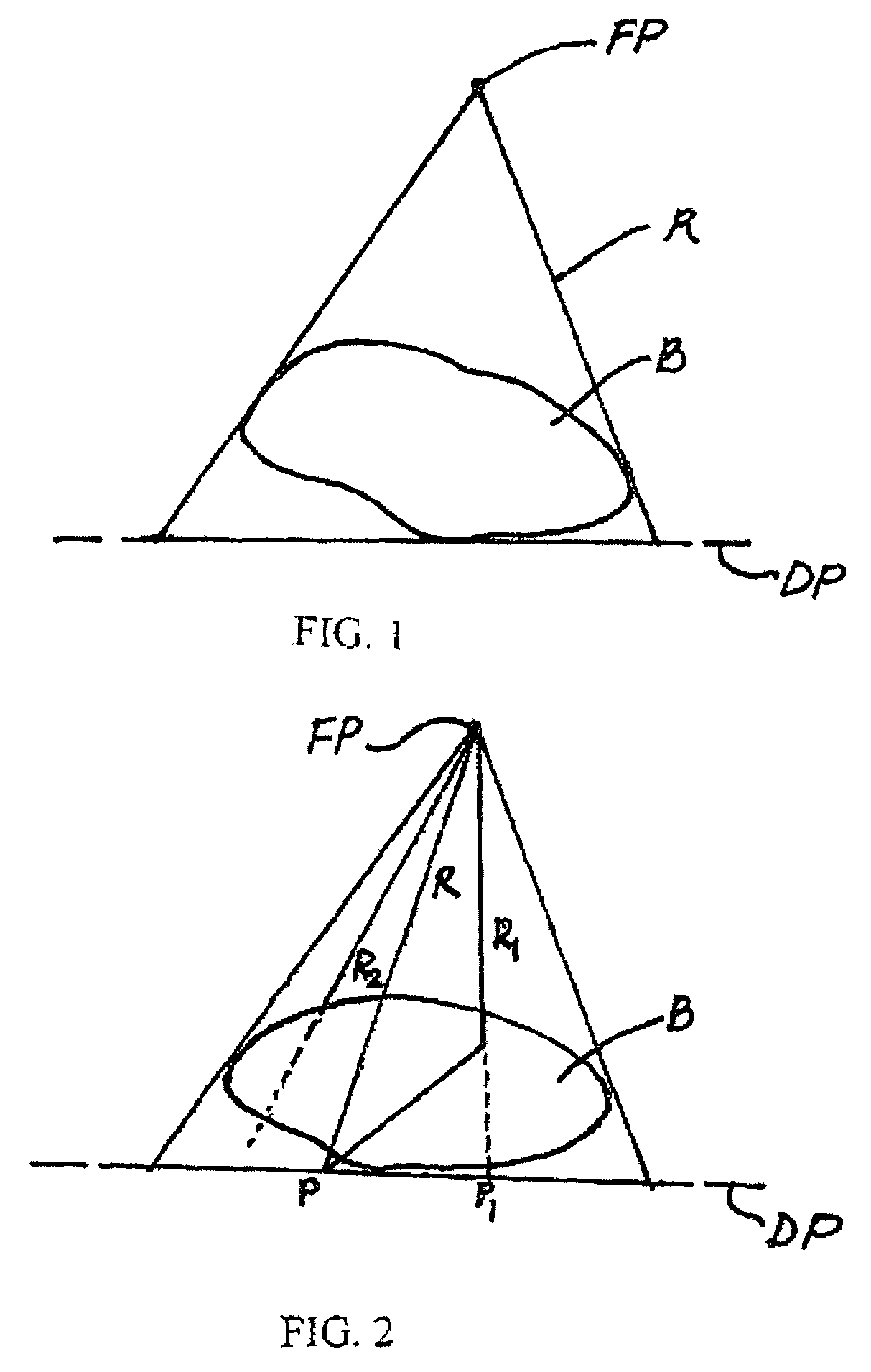
[0020]X-ray imaging uses the fact that x-rays “R” are extremely penetrating but are absorbed by the material “B” (such as a patient's body through which they pass. An x-ray image is the two-dimensional map of the x-ray absorption of the material “B” lying between an x-ray source located at a focal point “FP” and an X-ray detector located at a detector plane “DP”. FIG. 1 shows a typical medical x-ray imaging situation. The quality of the image depends on the fact that a significant fraction of the x-rays R are absorbed rather than scattered. Referring to FIG. 2, Ray R is emitted from the source located at the focal point FP and detected at point P by the X-ray detector located at the detector plane DP. Ray R1 scatters and is also detected at the point P. Ray R2 is totally absorbed and, therefore, not detected. In the making of an image, occurrences such as these happen many millions of times.

[0021]The fact that R1 scattered and was detected at P causes density along the ray R1 to be ...


PUM


Abstract

A method for manufacturing an anti-scatter grid including arranging a plurality of elongated metal ribbons of radio-opaque material so that each ribbon is substantially straight and lies in a plane that passes through a focal point of the grid, and placing the elongated ribbons under tension. A first sheet of radioluscent material is secured to top edges of the ribbons, and a second sheet of radioluscent material is secured to bottom edges of the ribbons. The ribbons are arranged such that the first and second radioluscent sheets are substantially parallel. Then the tension is removed from the ribbons.

Description

CROSS-REFERENCE TO RELATED APPLICATION[0001]The present application claims priority from U.S. Provisional Patent Application Ser. No. 60 / 470,176 filed on May 13, 2003, which is assigned to the assignee of the present application and incorporated herein by reference.FIELD OF THE INVENTION[0002]The present invention generally relates to the field of medical radiography, and more particularly to a method of making an X-ray anti-scatter grid for use in patient diagnostic imaging procedures.BACKGROUND OF THE INVENTION[0003]Scattered X-ray radiation (sometimes referred to as secondary or off-axis radiation) is generally a serious problem in the field of radiography. Scattered X-ray radiation is a particularly serious problem in the field of X-ray patient diagnostic imaging procedures, such as mammographic procedures, where high contrast images are required to detect subtle changes in patient tissue.[0004]Prior to the present invention, scattered X-ray radiation in patient diagnostic imagi...

Claims


Application Information

Patent Timeline
Patent Type & Authority Patents(United States)
IPC IPC(8): G21K1/00G21K1/10
CPCG21K1/10
Inventor DOBBS, JOHN M.TOBIN, STEPHEN M.
Owner ANLOGIC CORP (US)
Learn More