Image processing apparatus and method
a technology of image processing and apparatus, applied in the field of color matching, can solve the problems of no method established which determines viewing condition parameters, and no color matching result having high accuracy can be locally obtained
- Summary
- Abstract
- Description
- Claims
- Application Information
AI Technical Summary
Benefits of technology
Problems solved by technology
Method used
Image
Examples
first embodiment
[Concept of Color Matching]
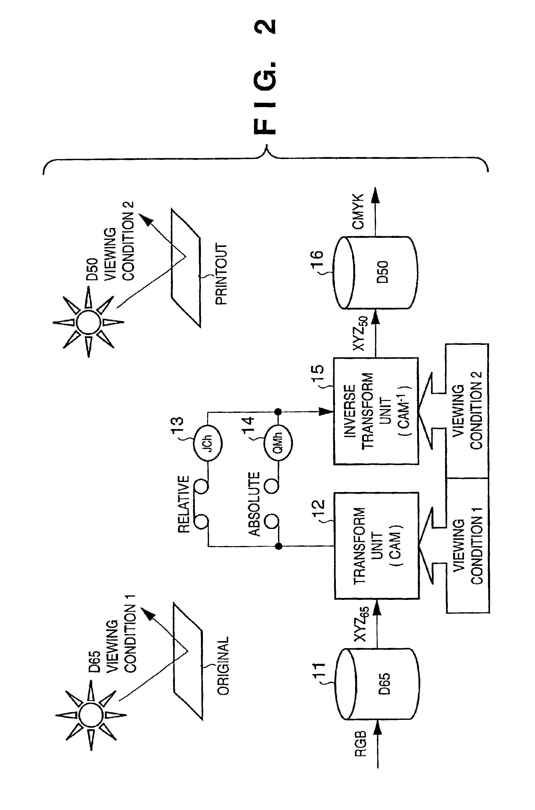
[0041]FIG. 2 is a view for explaining the concept of color matching.
[0042]In FIG. 2, reference numeral 11 denotes a conversion matrix or conversion lookup table (LUT) for transforming data depending on an input device into device-independent color space data which is based on the white point reference of environmental light at the input side; 12, a color appearance model transform unit (CAM) for transforming the data obtained from the conversion LUT 11 into a human color appearance space JCh or QMh; 13, JCh (or JCH) which is a color appearance space relative to the reference white point of environmental light; 14, QMh (or QMH) which is an absolute color appearance space which changes its size in accordance with an illuminance level; 15, a color appearance model inverse transform unit for transforming the human color appearance space JCh or QMh into device-independent color space data based on the reference white point of environmental light at the output s...
third embodiment
[0114]An image processing apparatus of the third embodiment according to the present invention will be described below. In the third embodiment, the same reference numerals as in the first embodiment denote the same parts, and a detailed description thereof will be omitted.
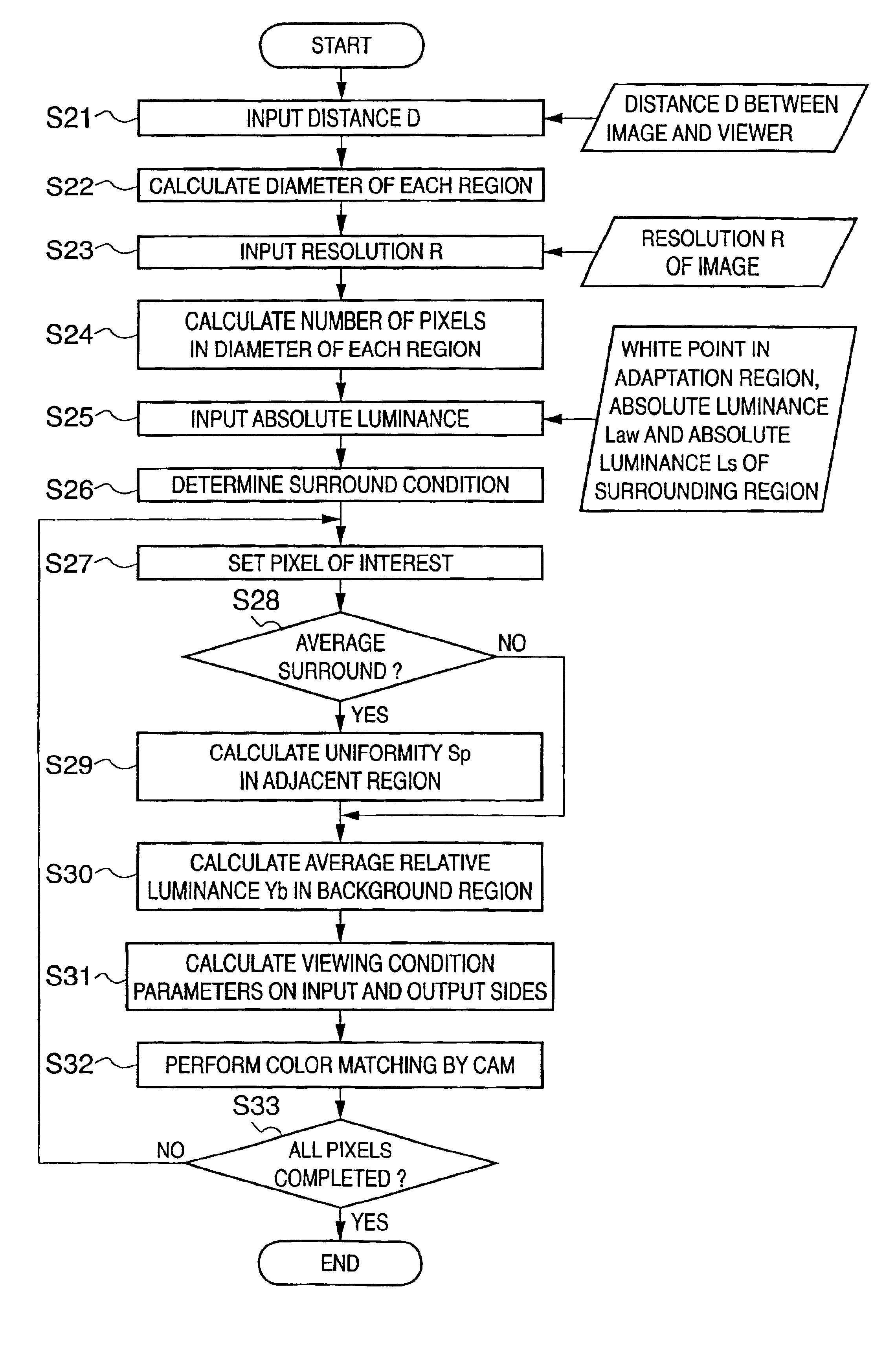
[0115]In step S21 of FIG. 3, a user inputs a distance D between an image and a viewer. This process can be automated by the use of a distance measurement sensor. As an example, a distance measurement sensor which measures a distance on the basis of the reflection time of infrared radiation is placed on a monitor or a viewing box (FIG. 9).
[0116]If a measurement sensor is difficult to install or is not connected to a host, the distance D can be manually set. It is of course also possible to input a numerical value (distance) displayed on a measurement sensor when the sensor is offline (not connected to a host machine).
[0117]Furthermore, in processing near the edge of an image, a relative luminance value for an omitt...
fourth embodiment
[0123]An image processing apparatus of the fourth embodiment according to the present invention will be described below. In the fourth embodiment, the same reference numerals as in the first embodiment denote the same parts, and a detailed description thereof will be omitted.
[0124]In the fourth embodiment, processing of detecting Ymax and Ymin and processing of calculating average relative luminance Yb of a background region in the above-described embodiments are executed at a high speed.
[Detection of Ymax and Ymin in Adjacent Region]
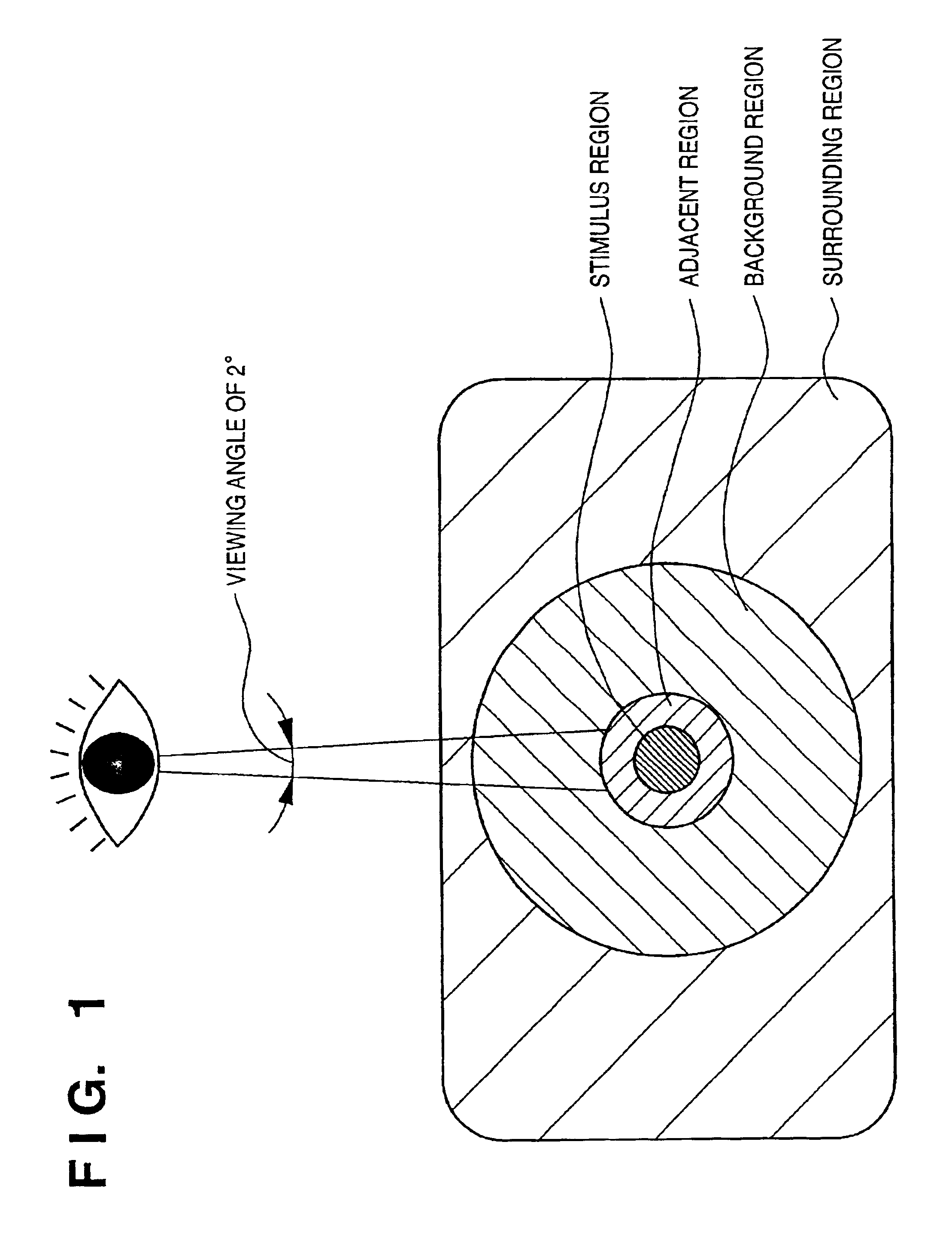
[0125]For processing of calculating uniformity Sp in an adjacent region in an image (step S29 in FIG. 3), whether a field angle of 4° or less can evenly be approximated to one color chip is determined. That is, calculation need not always be performed using a relative luminance Y.
[0126]For example, Rmax, Rmin, Gmax, Gmin, Bmax, and Bmin are obtained in an adjacent region in association with the channels of an RGB image, and uniformities in the channels,...
PUM
 Abstract
Description
Claims
Application Information
 - R&D
- Intellectual Property
- Life Sciences
- Materials
- Tech Scout
- Unparalleled Data Quality
- Higher Quality Content
- 60% Fewer Hallucinations
Browse by: Latest US Patents, China's latest patents, Technical Efficacy Thesaurus, Application Domain, Technology Topic, Popular Technical Reports.
© 2025 PatSnap. All rights reserved.Legal|Privacy policy|Modern Slavery Act Transparency Statement|Sitemap|About US| Contact US: help@patsnap.com


