System and method for displaying storage system topology

a storage system and topology technology, applied in the field of management of storage systems, can solve the problems of complicated connection between hosts and storages, significant problems may not take place, so as to achieve the effect of fine and user-friendly

Inactive Publication Date: 2006-07-04
HITACHI LTD
View PDF12 Cites 39 Cited by
  • Summary
  • Abstract
  • Description
  • Claims
  • Application Information

AI Technical Summary

Benefits of technology

[0010]It is an object of the present invention to provide a method of managing a plurality of storages and volumes in a more fine and more user-understandable manner in a network environment where the storages and volumes are interconnected through different physical communication lines such as the Ethernet and Fibre Channel.

Problems solved by technology

This, however, leads to the complicated connections between the hosts and the storages.
In a case that a simply configured network includes a small number of hosts and storages, each user of the connected apparatuses can easily manage the apparatuses, so that a significant problem may hardly take place.
That is, if a user replaces an existing apparatus with a new one and installs software into the apparatus, a problem may hardly take place.
On the other hand, in a large-scaled complicated network or a large-scaled LAN having LANs interconnected therewith, the adverse effect given by a possible problem ripples through the network and the search, and the diagnosis and the countermeasure of the problem is made more difficult.
It means that the storage management is likely to be more and more complicated.
The conventional management software that manages only the LAN or SAN cannot cope with the complicated management of the storages.

Method used


Image

  • System and method for displaying storage system topology
  • System and method for displaying storage system topology
  • System and method for displaying storage system topology

Examples


Embodiment Construction

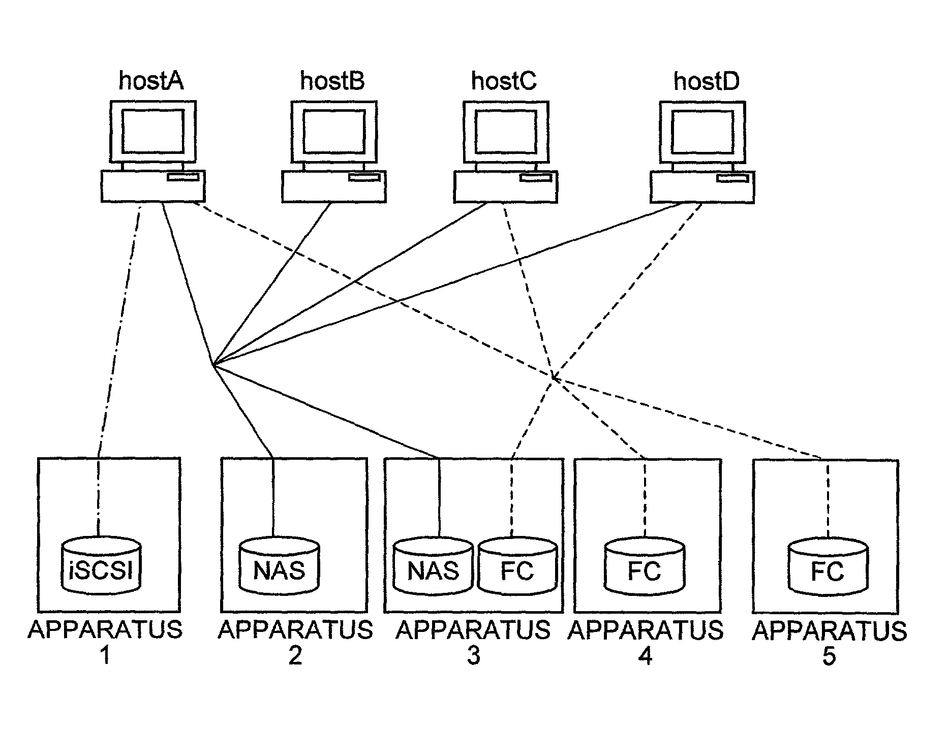
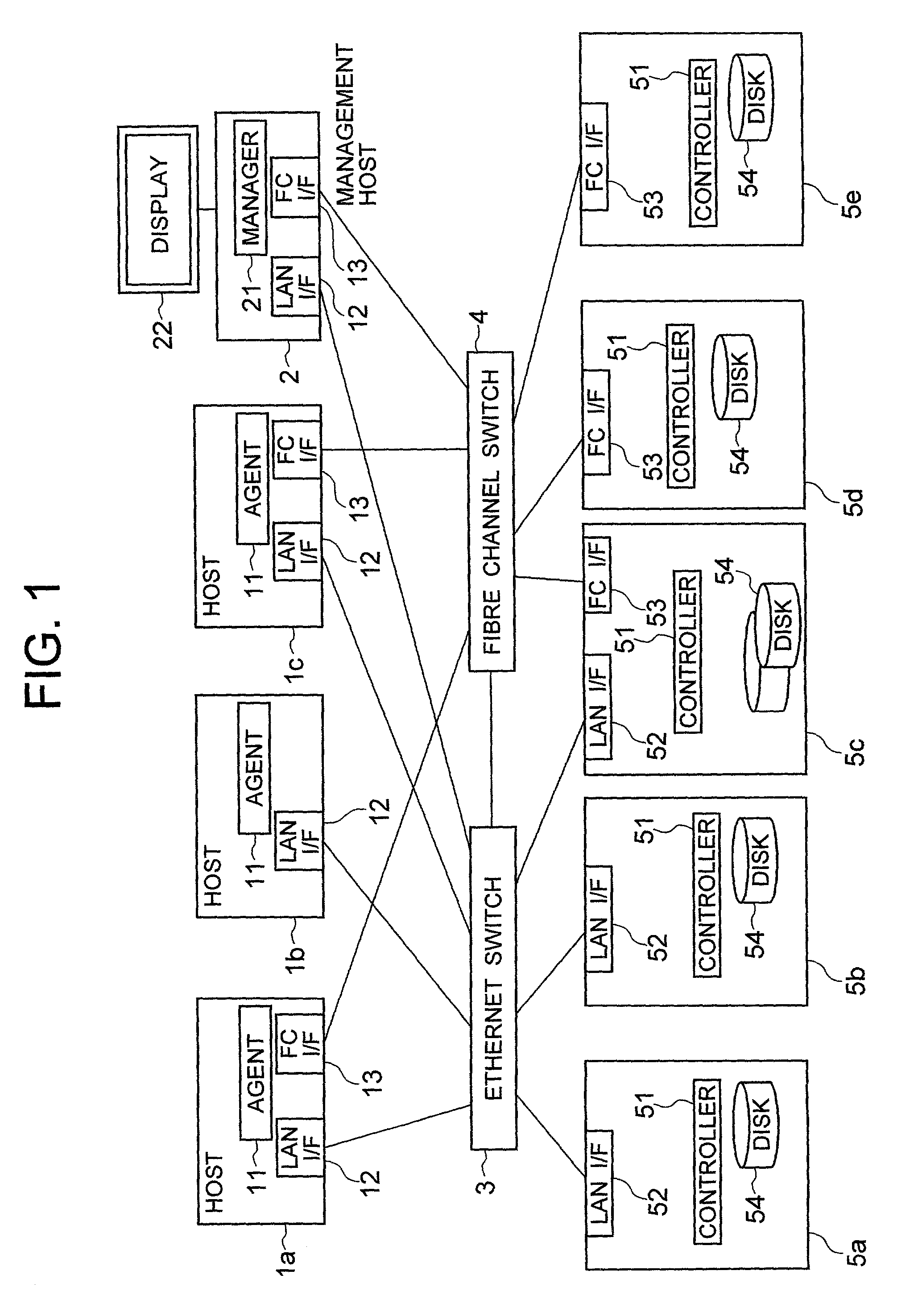
[0040]FIG. 1 is a block diagram showing an exemplary configuration of an embodiment of a computer system to which the present invention applies. The computer system is configured to have a plurality of hosts, that is, a host 1a, a host 1b and a host 1c (collectively called hosts 1), a management host computer 2, an Ethernet switch 3, a Fibre channel switch 4, and a plurality of storage subsystems 5a to 5e.

[0041]The host 1 includes an Ethernet interface 12 (abbreviated as LAN I / F) and a Fibre channel interface 13 (abbreviated as FC I / F). The host 1 makes access to a plurality of storage subsystems through the Ethernet switch 3 and the Fibre channel switch 4. Further, the host 1 includes the software called an agent 11, which is served to communicate with the management host 2.

[0042]The management host 2 includes a manager 21 through which the information is transferred with each agent 11. Like the host 1, the management host includes a LAN I / F 12 and an FC I / F 13 through which it ma...


PUM


Abstract

A management display method according to each type of interfaces and devices is provided in an environment where host computers are interconnected with storage apparatuses through plural types of interfaces. The management host computer includes a display apparatus and allows a user to select a physical view for displaying a physical topology between each host and storage subsystems or a logical view for displaying a connecting relation between the devices of the storage subsystem and each host computer. The management host computer operates to collect the information of the Fibre channel interface and the Ethernet interface and the information about an access limitation of each device, included in each host computer and storage subsystem and then to display the connecting relation according to the display method (view) selected by the user, based on the collected information.

Description

BACKGROUND OF THE INVENTION[0001]The present invention relates to a method of managing a storage system included in an information processing system, and more particularly to the method of managing a system in a computer system having a plurality of computers interconnected with a plurality of storage apparatuses through physical mediums such as Fibre Channel and Ethernet.[0002]In general, a computer system often used in an office, an enterprise or the like includes a plurality of host computers (each of which is referred simply to as a host) interconnected through a network like Ethernet. This network is called LAN (Local Area Network). The LAN may be connected with another network so that the LAN be built in a large-scale system, ranging from a regional system to the worldwide system as the largest area system.[0003]With recent advent of the Fibre Channel that realizes a faster data transfer, the concept of a SAN (Storage Area Network) appears which includes a plurality of hosts c...

Claims


Application Information

Patent Timeline
Patent Type & Authority Patents(United States)
IPC IPC(8): G06F15/16G06F13/14G06F13/00H04L12/24H04L12/28
CPCH04L41/22H04L41/12
Inventor KITAMURA, MANABUTAKAMOTO, KENICHI
Owner HITACHI LTD
Why Eureka
Try Eureka