Pouring spout

a technology of spraying spouts and spraying pans, which is applied in the field of spraying spouts, can solve the problems of affecting so as to facilitate the removal of liquid materials

Inactive Publication Date: 2006-07-11
HANELL EDWARD G
View PDF24 Cites 18 Cited by
  • Summary
  • Abstract
  • Description
  • Claims
  • Application Information

AI Technical Summary

Benefits of technology

[0009]Briefly, and in general terms, the present invention provides a new and improved pouring spout for providing a conduit for the discharge of the contents of a closed container containing, for example, fluids or granulated materials. In particular, the inventive pouring spout facilitates the removal of liquid materials typically used in the building and construction industry such as, for example, paint. The invention enables measured volumes of, for example, paint, to be removed from the closed container which can be a standard gallon container. Insertion of the inventive pouring spout into a top surface or lid of the closed container enables the measured volume of paint to be dispensed to a second container, such as a roller pan, without the spillage typically associated with removing paint from a gallon container.
[0011]The cylindrical inner housing also includes an anti-drip collar which serves to prevent drainage or dripping of paint once the pouring operation has ceased. Further, the anti-drip collar also functions to secure the removable cap to the pouring spout. A plurality of guide ribs are formed onto the external surface of the cylindrical inner housing which are intended to cooperate with a corresponding plurality of slots formed in a top ring, attached to the top of the outer safety sleeve. The guide ribs serve to keep the outer safety sleeve aligned with the cylindrical inner housing and to provide an interference fit there between. A raised ring is formed on the bottom of the cylindrical inner housing to serve as a stop when the cylindrical inner housing reaches the top surface or lid of the closed container during insertion of the punch blades. A seal washer is positioned between the raised ring and the top surface or lid of the closed container to prevent leakage of paint at that interface.

Problems solved by technology

Opening containers which contain liquid or granular material while simultaneously avoiding spillage has always posed a challenge to the tradesman in the work environment.
Once the lid is removed from the paint can, spillage of the contents is very common.
This is the case since the gallon paint container cannot accommodate the larger roller apparatus utilized to transfer the paint to the flat surface.
It is during the transfer of the volume of paint from the gallon container to the roller pan that spillage most often occurs.
Even if the proper procedures are followed, i.e., the use of plastic drop clothes and other protective means, spillage of the paint while pouring from the paint container into the roller pan is very common.
This situation often results in an unsatisfactory mess and wasted time since the spillage obviously must be contained immediately.
However, no patent or combination of patents discovered teaches or discloses either individually or in combination the use of a pair of opposing stainless steel punch blades, projection spurs, locking notches, and a sliding plastic safety sleeve in combination with the pouring spout construction.

Method used


Image

  • Pouring spout
  • Pouring spout
  • Pouring spout

Examples


Embodiment Construction

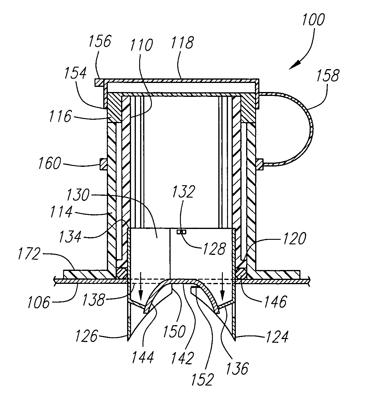
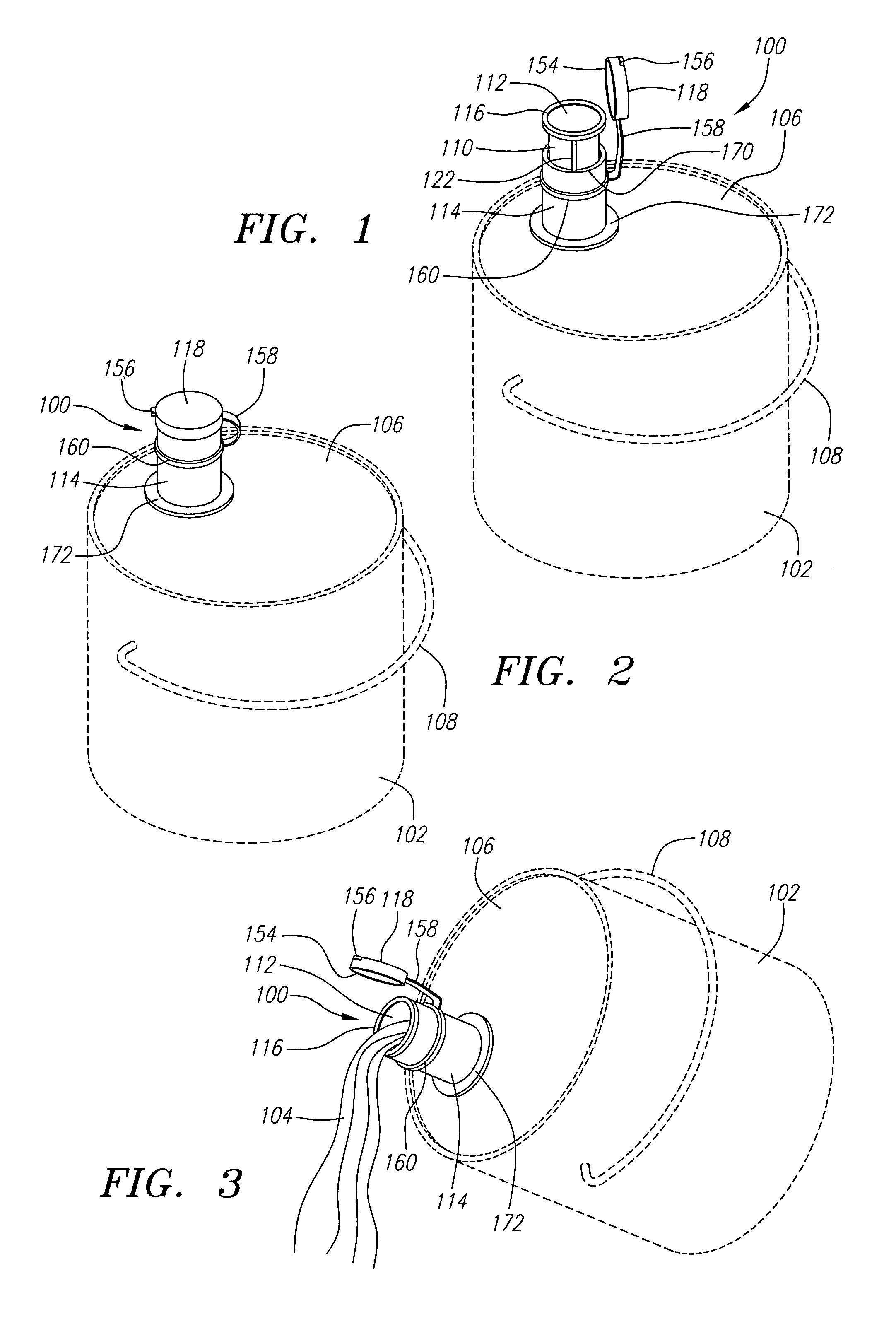
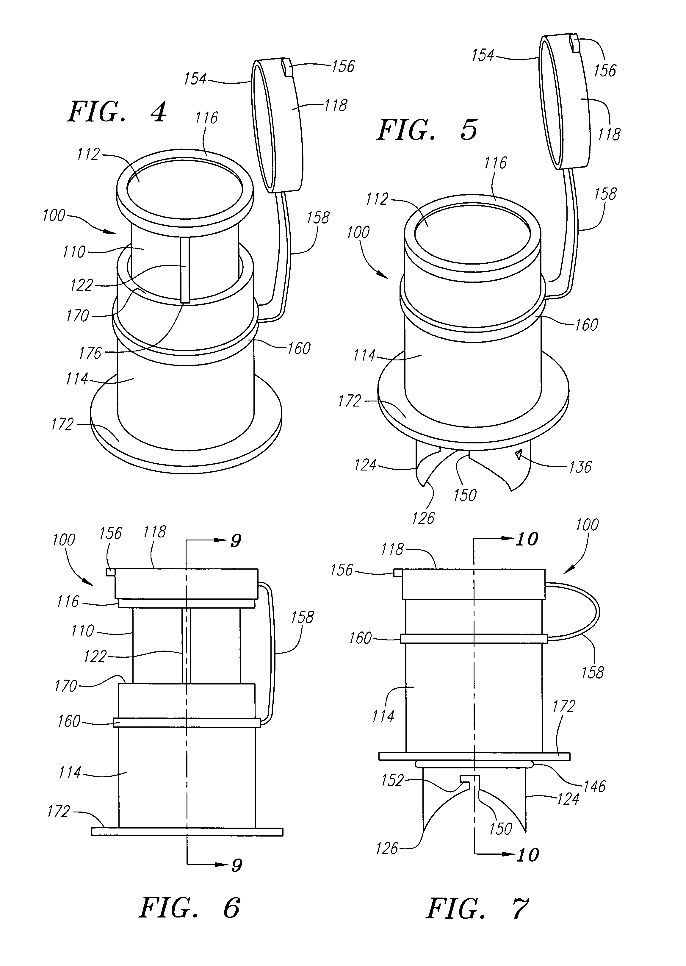
[0029]The present invention is a pouring spout 100 intended to provide a discharge conduit for the contents of a closed container 102 which can contain, for example, liquids or granulated materials 104. The liquids or granulated materials 104 might be typically employed in the building or construction industry where a suitable example is paint or other pourable liquid. Thus, the inventive pouring spout 100 can facilitate the removal of the paint from the closed container 102 in measured volumes. It is noted that the closed container 102 can be a standard gallon paint container having a removable top surface or lid 106 typically removed with a common tool such as a screwdriver. Manual insertion of the inventive pouring spout 100 into the top surface or lid 106 of the closed container 102 enables a measured volume of the liquid or granulated material 104, i.e., the paint, to be dispensed from the closed container 102 to a second container such as a roller pan (not shown). By utilizing...


PUM


Abstract

A pouring spout for use in providing a conduit for the discharge of the contents of a closed container containing fluids or granulated materials includes a cylindrical inner housing having an open top end and a removable tethered cap. A pair of opposing punch blades affixed to the cylindrical inner housing is provided for insertion into a top surface of a container where the cylindrical inner housing and the punch blades serve to provide a discharge conduit for the container. A projection spur is formed on each of the punch blades for forcing open the top surface of the container. An outer safety sleeve is provided for covering the punch blades when the punch blades are withdrawn from the top surface of the container.

Description

BACKGROUND OF THE INVENTION[0001]1. Technical Field[0002]The present invention relates to pouring spouts for containers. More specifically, the present invention relates to methods and apparatus for a pouring spout having a removably capped, cylindrical inner housing in combination with a pair of stainless steel opposing punch blades for insertion into a closed container, the spout serving as an exit conduit for the container contents, where an outer safety sleeve is provided to cover the punch blades when the spout is not in use.[0003]2. Background Art[0004]Opening containers which contain liquid or granular material while simultaneously avoiding spillage has always posed a challenge to the tradesman in the work environment. Containers, typically of the gallon and quart variety, which contain fluids, paints, water seals, granular materials and the like usually include a top lid. Often, the container lid will include a lip or edge which is designed to facilitate the opening of the c...

Claims


Application Information

Patent Timeline
Patent Type & Authority Patents(United States)
IPC IPC(8): B67D5/00B67B7/48B67D3/00B67D3/04B67D99/00
CPCB67B7/26
Inventor HANELL, EDWARD G.
Owner HANELL EDWARD G
Why Eureka
Try Eureka