
Disk blade bearing hub assembly

a technology for bearing hubs and disk blades, which is applied in the direction of bearing components, bearings, shafts and bearings, etc., can solve the problems of premature bearing failure, and high load on the bearing for agricultural tillage and planting equipment, so as to reduce maintenance and improve the effect of bearing life and reduce maintenan

Active Publication Date: 2006-07-11
DEERE & CO
View PDF11 Cites 17 Cited by
  • Summary
  • Abstract
  • Description
  • Claims
  • Application Information

AI Technical Summary

Benefits of technology

[0006]It is another object of the present invention to provide an improved disk blade bearing hub assembly which is simple, economical and compact in construction and which reduces maintenance compared to at least most previously available assemblies. It is yet another object to provide such an assembly which has unique repetitive sealing system for protecting the primary bearing seal.
[0007]It is a further object of the invention to provide an improved disk blade bearing hub assembly particularly useful for individually mounted bearing blade assemblies. It is another object to provide such an assembly which is able to withstand extended adverse operations, including operation in wet fall soil without deterioration of the primary seal or the disk blade bearing.
[0008]It is a further object to provide an improved single disk blade bearing hub assembly which is substantially narrower than at least most previously available single disk blade hub assemblies for improved trash and soil flow. It is another object to provide such an assembly which facilitates close side-by-side disk blade mounting near the center of a machine adjacent the intersection of gang tube halves. It is another object to provide such an assembly providing better disk scouring than at least most previously available single disk hub assemblies.
[0009]A maintenance free repetitive sealing system for a disk blade bearing hub utilizes an integrated system of components to seal and protect the primary bearing seal. The blade side of the spindle includes a hub overlap portion which deflects dirt, keeps large debris out, and prevents wrapping. A plastic seal protector keeps dirt and debris from pushing directly into external seal lips of a multiple lip seal. The lip seal provides positive sealing and is backed up by a grease layer barrier. The hub overlap, plastic seal protector, multiple lip seal and grease barrier protect the bearing seal. The back side of the bearing hub is positively sealed with a protected O-ring and dust cap combination. The cap combination also protects the blade mounting hardware threads and nut. The width of the hub assembly is only about three-fourths that of assemblies utilizing a more conventional arbor bolt and double nut construction.
[0010]The location of the dust cap on the back side of the housing eliminates a bulky protrusion at the center of the disk blade so the blade scours more easily. In addition, the cap is recessed within the housing and does not protrude. The bearing is sealed, does not require re-greasing, and does not require torquing to set bearing end play. The bearing seal counteracts normal tapered roller pumping action and keeps the grease in front of the bearing rollers. A low cost, standard grade bolt can be utilized to extend through the spindle and clamp the blade against the outer end of the spindle.

Problems solved by technology

Disk blade bearings for agricultural tillage and planting equipment are subjected to high loads in a severe environment.
Bearing seal failure leading to premature bearing failure has been an ongoing problem.
However, the frequent greasing is time-consuming and reduces the productivity of the implement.
The individually mounted blades create two new problems relative to the grease method of flushing the bearings.
First, wetter field conditions are harder on the seals.
Mud packs into the seal area and ultimately works into the bearing to cause permanent damage to the seals.
The combination of more grease fittings to grease and an increased maintenance frequency results in a difficult, time-consuming maintenance chore.
Disk mounted bearings require a dust cap on the disk hub which hampers blade scouring and the taper roller bearings must be carefully torqued during the assembly process.
The single seal often fails to adequately protect the bearings from contamination by dirt and debris.

Method used


Image

  • Disk blade bearing hub assembly
  • Disk blade bearing hub assembly
  • Disk blade bearing hub assembly

Examples


Embodiment Construction

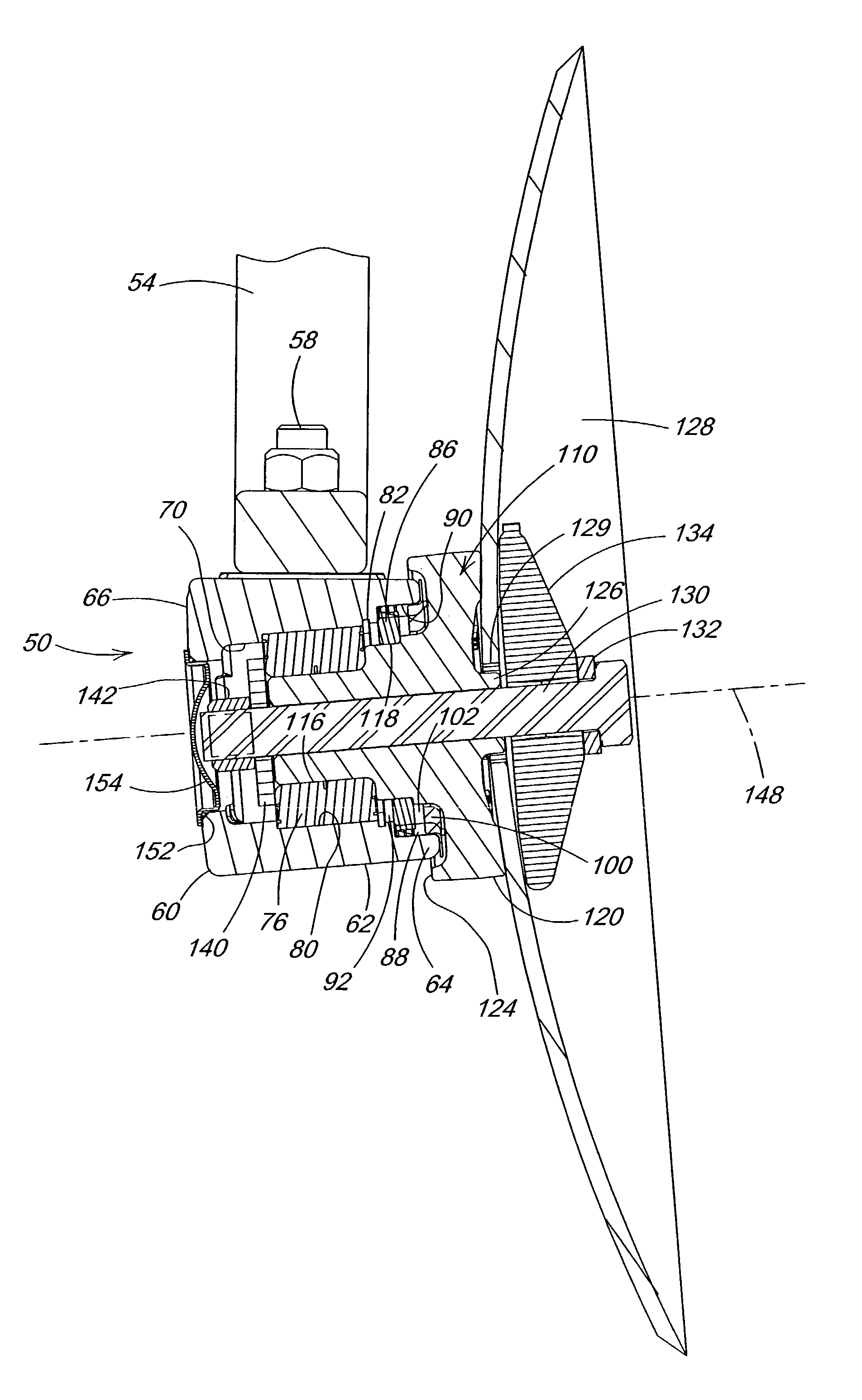
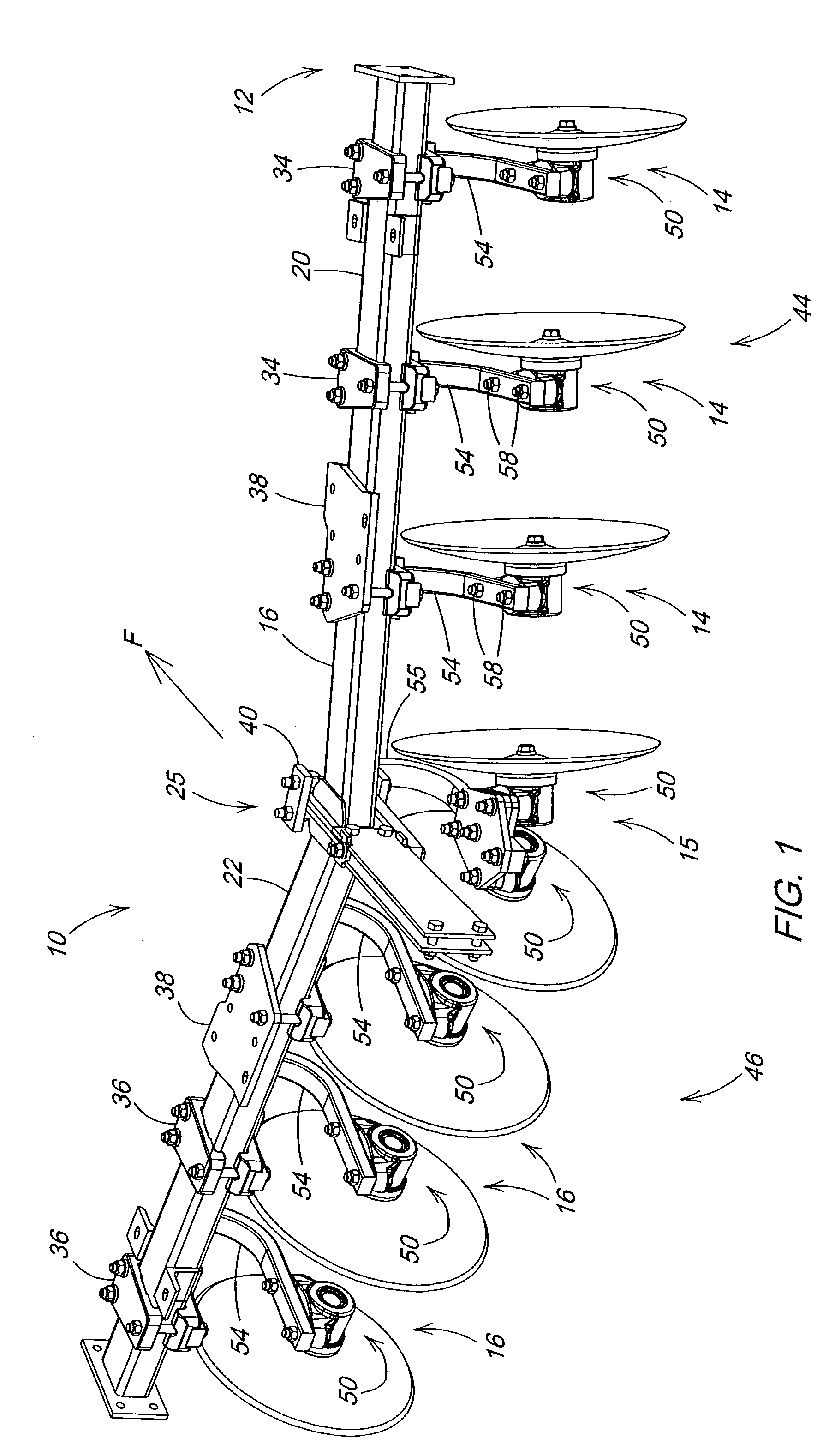
[0015]Referring to FIG. 1, therein is shown a portion of an agricultural tillage implement 10 such as a mulch ripper or other implement having a frame 12 supporting disk blade assemblies indicated generally at 14, 15 and 16. The implement frame 12 includes angled gang tubes 20 and 22 forming opposite halves centrally connected by gang tube plate bracket structure 25. Standard bracket structures 36, 38 and 40 connect the disk blade assemblies 14, 15 and 16 to the tubes 20 and 22 to generally define disk gangs 44 and 46 angled with respect to a direction transverse to the forward direction (F).

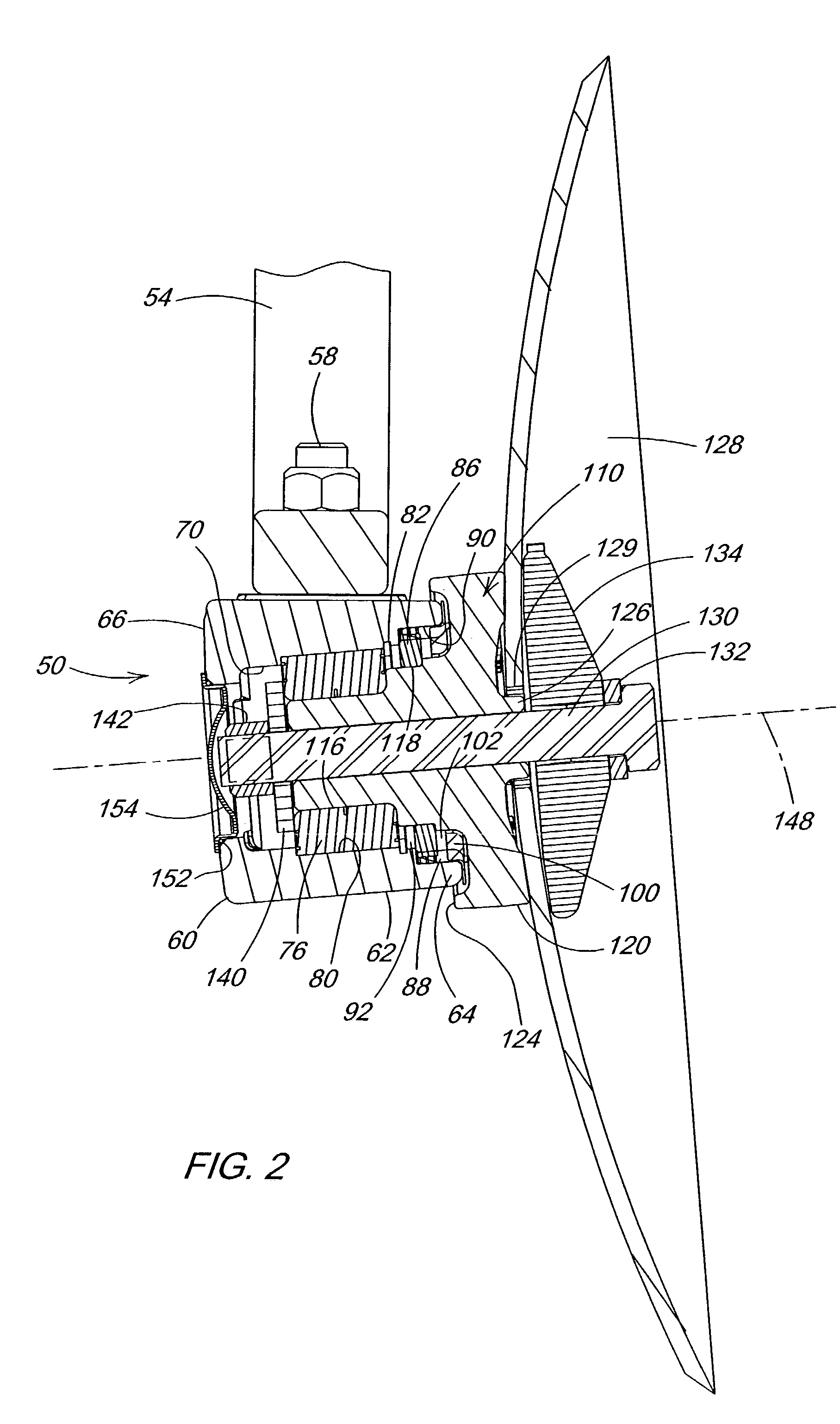
[0016]The disk blade assemblies 14, 15 and 16 are shown with identical disk bearing hub assemblies 50 (FIGS. 2 and 3). The hub assemblies 50 are connected to the lower tool-receiving ends of curved shanks or C-springs 54 and 55 in either concave right (assemblies 14) or concave left (assemblies 16) configuration. The hub assemblies 50 are reversible on the C-springs, and therefore a single hub c...


PUM


Abstract

A maintenance free repetitive sealing system for a disk blade bearing hub utilizing an integrated system of components to seal and protect the primary bearing seal. The blade side of the spindle includes a hub overlap portion which deflects dirt, keeps large debris out, and prevents wrapping. A plastic seal protector keeps dirt and debris from pushing directly into external seal lips of a multiple lip seal. The lip seal provides positive sealing and is backed up by a grease layer barrier. The hub overlap, plastic seal protector, and grease barrier protect the bearing seal. The back side of the bearing hub is positively sealed with a protected O-ring and dust cap combination. The cap combination also protects the blade mounting hardware threads and nut.

Description

FIELD OF THE INVENTION[0001]The present invention relates generally to bearings for agricultural disk blades and, more specifically, to a disk blade bearing hub assembly having tapered roller bearings and multiple seals.BACKGROUND OF THE INVENTION[0002]Disk blade bearings for agricultural tillage and planting equipment are subjected to high loads in a severe environment. Bearing seal failure leading to premature bearing failure has been an ongoing problem. For years, the main attempt at a solution to the problem has been the utilization of a grease fitting with frequent scheduled greasing to flush contaminates out of the bearing. For most disk gang bearing applications, frequent greasing has been a generally acceptable practice since each bearing normally supports from three to six blades and the grease fittings are reasonably accessible. However, the frequent greasing is time-consuming and reduces the productivity of the implement.[0003]Recently developed combination tillage tools ...

Claims


Application Information

Patent Timeline
IPC IPC(8): F16C33/76A01B71/04
CPCA01B71/04
Inventor RUCKLE, JARROD RAYCOX, PHILIP DAVIDBIERL, JAMES FRANKLIN
Owner DEERE & CO
Learn More