Modular tapered reamer for bone preparation and associated method

a bone preparation and reamer technology, applied in the field of orthopaedics, can solve the problems of inability to stabilize the joint, difficult to achieve the effect of ensuring the stability of the joint, and difficulty in adjusting the position of the soft tissue, so as to improve the positioning of the prosthesis and optimize the soft tissue position

Active Publication Date: 2006-07-11
DEPUY PROD INC
View PDF63 Cites 119 Cited by
  • Summary
  • Abstract
  • Description
  • Claims
  • Application Information

AI Technical Summary

Benefits of technology

[0024]Another technical advantage of the present invention includes the ability of the modular reamer of the present invention to provide optimal biomechanics. Because of the shallow taper angle, axial positioning is difficult. The present invention provides for improved positioning of the prosthesis and an optimization of the soft tissue position and the reduction of soft tissue laxity. For example, according to one aspect of the present invention, the modular reamer permits the mounting of a proximal trial on the reamer while the tapered reamer is still in position in the canal. The surgeon has the greater certainty that the trial reduction biomechanics are correct if he can do the trial reduction off the reamer. This ensures that the relative references are maintained. By eliminating the additional step of removing the reamer and implanting a distal trial as well as the proximal trial, the accuracy of the trial and resultant implant positioning is improved. The improved positioning of the prosthesis provides for improved soft tissue positioning and optimum biomechanics. Thus, the present invention provides for optimum biomechanics.
[0025]Another technical advantage of the present invention includes improved anteversion or the angular orientation of the joint in the body. For example, according to another aspect of the present invention, the driver may be separated from the distal reamer while the distal reamer is still in position in the bone canal and a proximal trial may be positioned on the reamer. The trialing of the prosthesis on the reamer allows for relative rotational position and provides for improved accuracy of the positioning of the trial and therefore improved anteversion of the joint in the body. Thus, the present invention provides for improved anteversion of the joint in the body.
[0026]Yet another technical advantage of the present invention includes a reduction in the surgery time, which reduces the time the patient is at risk for surgery related complications. For example, according to one aspect of the present invention, the driver may be removed from the distal reamer while the distal reamer is still in position in the canal and a proximal trial may be positioned on the distal reamer. The prosthesis may thus be trialed off the reamer. Thus, the additional step of removing the reamer and positioning a distal trial in the cavity is eliminated thereby reducing the steps necessary for the procedure and the corresponding additional time for the removal of the reamer and the placement of the distal trial. Thus, the present invention provides for reduced surgery time and reduced patient complications during surgery.
[0027]Yet another technical advantage of the present invention includes the ability to use the medullary canal of the long bone or femur as a reference for the proper positioning of the implant, particularly when a revision procedure is performed in which the normal bone are landmarks, such as the greater and lesser trochanter, (some or all) are no longer present. For example, according to one aspect of the present invention, a proximal trial is placed on a reamer which is used to ream the medullary canal of the long bone or femur. The reamer remains in the canal after the reaming has been performed. The trialing can thus be performed from the reamer. Thus, the present invention provides for the use of the medullary canal of the long bone or femur as a reference for the proper positioning of the implant.
[0028]By being able to trial off the reamers, one can eliminate a whole tray of instruments which reduces cost and system complexity.

Problems solved by technology

Currently in total hip arthroplasty, a major critical concern is the instability of the joint.
Dislocation is particularly a problem in total hip arthroplasty.
The combination of all these biomechanic options is rather complex.
Improper version can lead to abnormal biodynamics, dislocation and patient dissatisfaction.
However, it is a more challenging issue with the advent of stems with additional modularity.
Therefore, the anteversion is limited.
These monolithic stems have limited flexibility for rotational alignment since the distal stem must follow the bow of the patient's femur and this may not provide an operable biomechanical result.
Quite often the remaining bone is significantly compromised compared to a primary hip procedure.
Significant bone loss is observed, often with a lack of bone landmarks typically used for alignment.
The long stem trials do not have the transverse bolts and are thus not rotationally stable during trial reduction and therefore are not always used by the surgeon.
Each step of the process, for example, the positioning of the trial after the reaming and the positioning of the implant after the trialing provides for an additional location error in the proper placement of the prosthesis, as well as additional time for the surgical procedure.

Method used


Image

  • Modular tapered reamer for bone preparation and associated method
  • Modular tapered reamer for bone preparation and associated method
  • Modular tapered reamer for bone preparation and associated method

Examples


Embodiment Construction

[0068]Embodiments of the present invention and the advantages thereof are best understood by referring to the following descriptions and drawings, wherein like numerals are used for like and corresponding parts of the drawings.

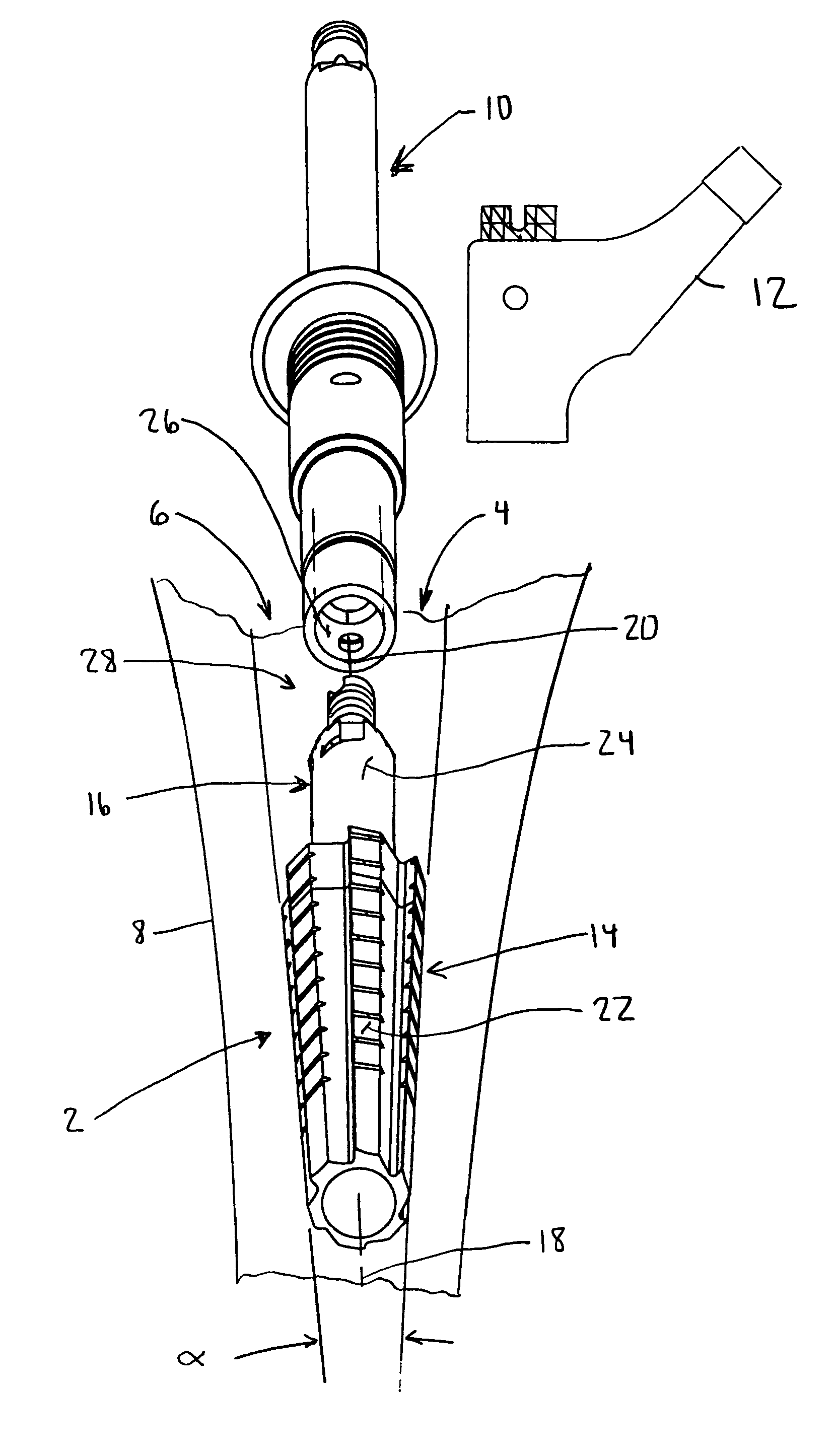
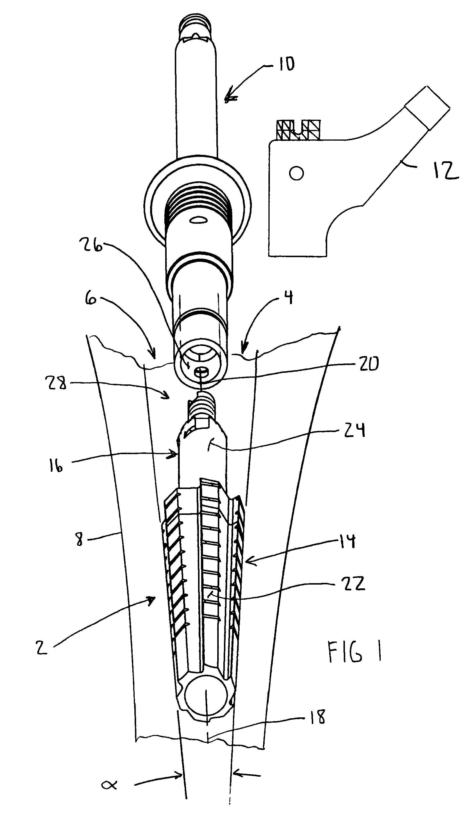
[0069]Referring now to FIG. 1, a reamer 2 according to the present invention is shown. The reamer 2 is utilized for preparing a cavity 4 in the intramedullary canal 6 of a long bone 8 with the use of a driver 10. The reamer 2 cooperates with an implant trial 12 to assist in performing a trial reduction. The reamer 2 includes a first portion 14 for preparation of the cavity 4 in the canal 6. The first portion 14 is adapted for placement at least partially in the cavity 4 of the long bone 8. The reamer 2 further includes a second portion 16 operably connected to the first portion 14. The second portion 16 is also connectable to the driver 10 to rotate the reamer 2. The reamer 2 is removably attachable to the trial 12 and to the driver 10.

[0070]As shown in FIG. 1...


PUM


Abstract

A kit (400) for use in performing joint arthroplasty is provided. The kit (400) includes a trial (12) and a reamer (2). The reamer (2) is for preparing a cavity (4) in the intramedullary canal (8) of a long bone (8) with the use of a driver (10) and to assist in performing a trial reduction. The reamer (2) includes a first portion (14) for placement at least partially in the cavity (4) of the long bone (8) and a second portion (16) operably connected to the first portion (14). The reamer (2) is removably connected to the driver (10) to rotate the reamer (2). The trial (12) is removably attachable to the reamer (2).

Description

CROSS-REFERENCE TO RELATED APPLICATIONS[0001]Cross reference is made to the following applications: DEP 670 entitled “ASSEMBLY TOOL FOR MODULAR IMPLANTS AND ASSOCIATED METHOD” and DEP 5083 entitled “NON-LINEAR REAMER FOR BONE PREPARATION AND ASSOCIATED METHOD” filed concurrently herewith which are incorporated herein by reference.TECHNICAL FIELD OF THE INVENTION[0002]The present invention relates generally to the field of orthopaedics, and more particularly, to an implant for use in arthroplasty.BACKGROUND OF THE INVENTION[0003]Patients who suffer from the pain and immobility caused by osteoarthritis and rheumatoid arthritis have an option of joint replacement surgery. Joint replacement surgery is quite common and enables many individuals to function properly when it would not be otherwise possible to do so. Artificial joints are usually comprised of metal, ceramic and / or plastic components that are fixed to existing bone.[0004]Such joint replacement surgery is otherwise known as jo...

Claims


Application Information

Patent Timeline
Patent Type & Authority Patents(United States)
IPC IPC(8): A61B17/00A61B17/16
CPCA61B17/162A61B17/1668A61B17/164
Inventor DANIELS, DAVID WAYNEJAGGERS, CHARLES WESLEYDWYER, KIMBERLY ANNMORROW, DAVID WILLIAMPARKER, BRAD ALANBERRY, DANIEL J.
Owner DEPUY PROD INC
Why Eureka
Try Eureka