Stereotactic computer assisted surgery method and system

Active Publication Date: 2009-08-20
STRYKER EURO OPERATIONS HLDG LLC
View PDF68 Cites 55 Cited by
  • Summary
  • Abstract
  • Description
  • Claims
  • Application Information

AI Technical Summary

Benefits of technology

[0021]In another aspect, the present invention is a system and method of computer assisted surgery (CAS) using stereotactic navigation with three-dimensional visualization, wherein an implant or implant system acts as a stereotactic device. The invention provides a reactive CAS system designed for use with mono-axial and poly-axial plates and nails. Based on the principles of stereotactics and 2D-3D matching, a system is provided that virtually suggests or gives indication of the optimal position of an implant by calculating such position. In addition, the system may also calculate screw lengths before drilling. Aided by image processing and virtual 3D visualisation, the system can achieve optimal biomechanics.
[0022]In addition, unlike existing navigation systems, the CAS system of the present invention is designed to b

Problems solved by technology

The implantation of plating and nailing systems is often a difficult task because operating room (OR) procedures are generally minimally invasive and thus placement is achieved by trial and error using fluoroscopy such as a C-arm apparatus, i.e., C-arm vision.
This generally leads to long operating times. Furthermore, during such a procedure, both the patient and the operator are exposed to significant amounts of radiation.
In addition, in some cases it may be impossible to determine the position of implant components (for example, the screws in the bone) with sufficient precision because the fluoroscopic image is only two-dimensional.
This may lead to misplacement or insertion of screws of improper length.
This, in turn, may cause high revision rates or even injuries (e.g., hip joint injury).
In order to ensure that these implant components do not extrude from the bone, it is thus sometimes necessary to position these implant components with an excessively large margin of error away from the edge of the bone.
In many i

Method used


Image

  • Stereotactic computer assisted surgery method and system
  • Stereotactic computer assisted surgery method and system
  • Stereotactic computer assisted surgery method and system

Examples


Embodiment Construction

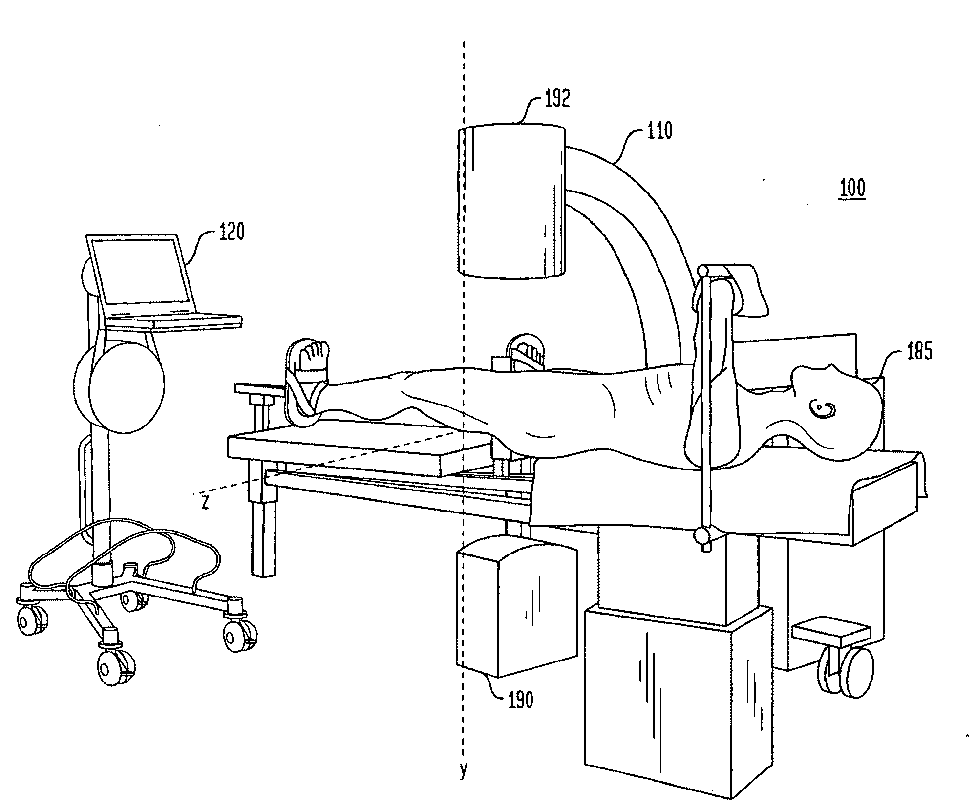
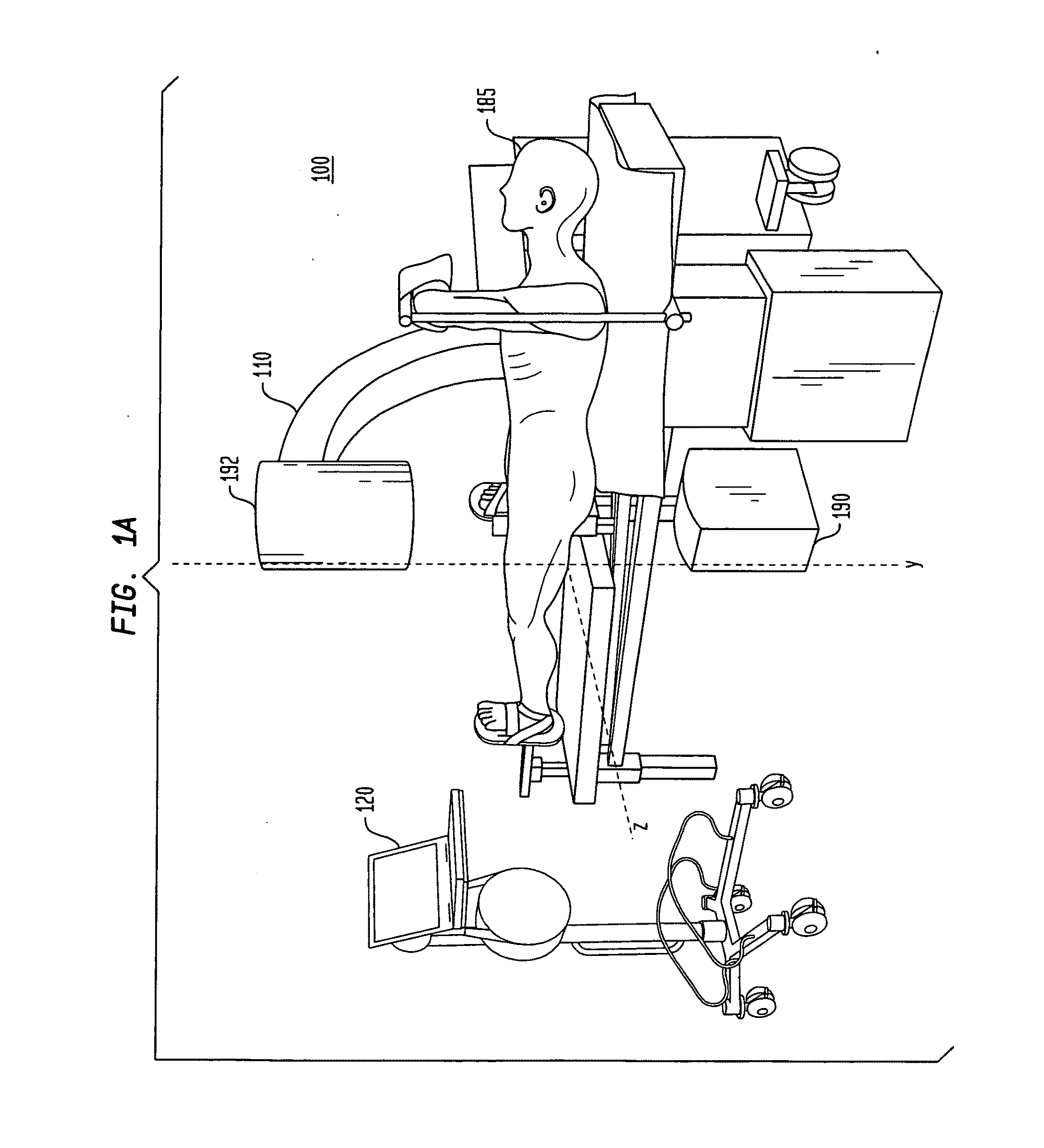
[0056]Generally, in one aspect, the system of the present invention is based on the registration of fluoroscopy images with an implant associated with a reference body. For example, the implant (e.g., an angle stable plate) may include the reference body or may be positioned in a predefined location in relation to the reference body, which is detected or recorded in a fluoro image. Thus, the actual spatial dimension and position of the implant can be determined by means of the correct identification and registration of the reference body in the fluoro images.

[0057]Where multiple related implants are included as part of the procedure, e.g., main implants and sub-implants, after registration of the main implant as described above, the location of any remaining sub-implants may be depicted virtually in the correct spatial position in relation to the fluoro images of the main implant. The sub-implants (e.g., screws of the associated angle stable plate) will be located in a fixed, pre-de...


PUM


Abstract

A computer assisted surgical system that includes an apparatus for imaging a region of interest of a portion of an anatomy of a subject; a memory containing executable instructions; and a processor programmed using the instructions to receive two or more two-dimensional images of the region of interest taken at different angles from the apparatus and process the two or more two-dimensional images to produce three dimensional information associated with the region of interest.

Description

CROSS-REFERENCE TO RELATED APPLICATION[0001]This application claims the benefit of the filing date of U.S. Provisional Patent Application No. 61 / 010,543 filed Jan. 9, 2008, the disclosure of which is hereby incorporated herein by reference.BACKGROUND OF THE INVENTION[0002]The invention relates to a system and method of computer assisted surgery (CAS) using stereotactic navigation with three-dimensional visualization, and more specifically to a CAS system that is reactive and does not disrupt operating room workflow procedures.[0003]A current method of inserting implants (consisting of, for example, a plate and associated screws) is typically accomplished by positioning the plate on the corresponding anatomical location and inserting the screws with the assistance of fluoroscopy. The implantation of plating and nailing systems is often a difficult task because operating room (OR) procedures are generally minimally invasive and thus placement is achieved by trial and error using fluor...

Claims


Application Information

Patent Timeline
IPC IPC(8): A61B6/00
CPCA61B17/1703A61B17/1721A61B17/1725A61B17/1728A61B17/744A61B17/746A61B2019/5295A61B19/5244A61B19/56A61B2019/507A61B2019/5238A61B2019/5287A61B19/5225A61B2090/363A61B2090/367A61B34/20A61B34/25A61B2090/376A61B2034/107A61B90/37A61B90/11A61B17/1753A61B2017/564
Inventor BLAU, ARNO
Owner STRYKER EURO OPERATIONS HLDG LLC
Why Eureka
Try Eureka