
Pulse-skipping PFM DC-DC converter using a voltage mode control loop

a voltage mode control and converter technology, applied in the direction of electric variable regulation, process and machine control, instruments, etc., can solve the problems of inherently less efficient converters when driving light loads, difficult current mode control, and negative impact on efficiency

Inactive Publication Date: 2006-07-11
NXP USA INC
View PDF7 Cites 40 Cited by
  • Summary
  • Abstract
  • Description
  • Claims
  • Application Information

AI Technical Summary

Problems solved by technology

However, when switched DC-DC converters are used, the converters are inherently less efficient when driving light loads because the power needed to switch the large power field-effect-transistors (FETs) is comparable or greater than the energy transferred to the load.
However, current mode control is difficult, because it requires sensing currents, which is difficult to sense due to noise, offsets and circuit complexity.
Also, sensing a current usually requires a sensing resistor, which negatively impacts efficiency.
Thus, sensing current in a switched DC-DC converter may be difficult to do or may be undesirable.

Method used


Image

  • Pulse-skipping PFM DC-DC converter using a voltage mode control loop
  • Pulse-skipping PFM DC-DC converter using a voltage mode control loop
  • Pulse-skipping PFM DC-DC converter using a voltage mode control loop

Examples


Embodiment Construction

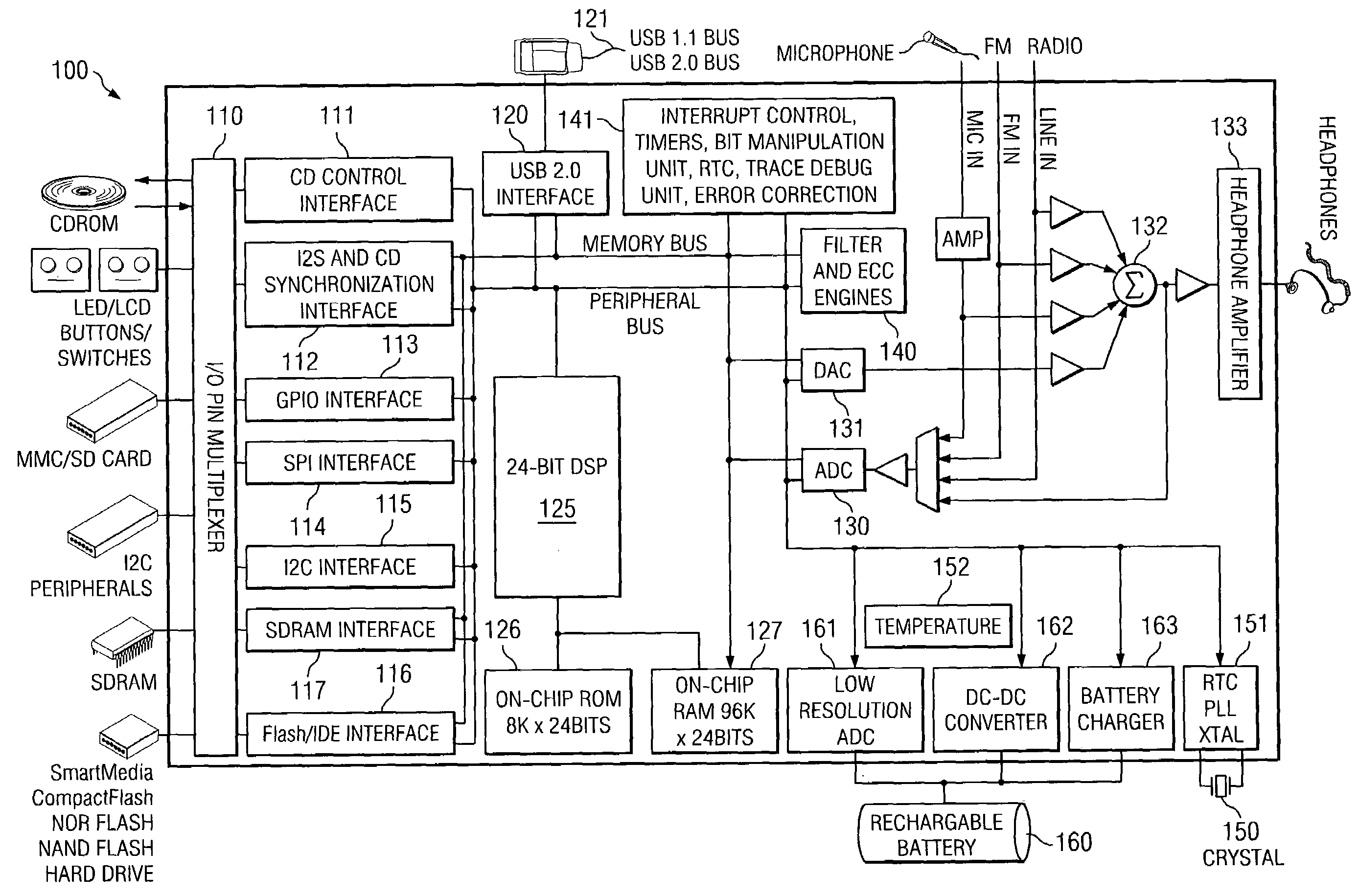
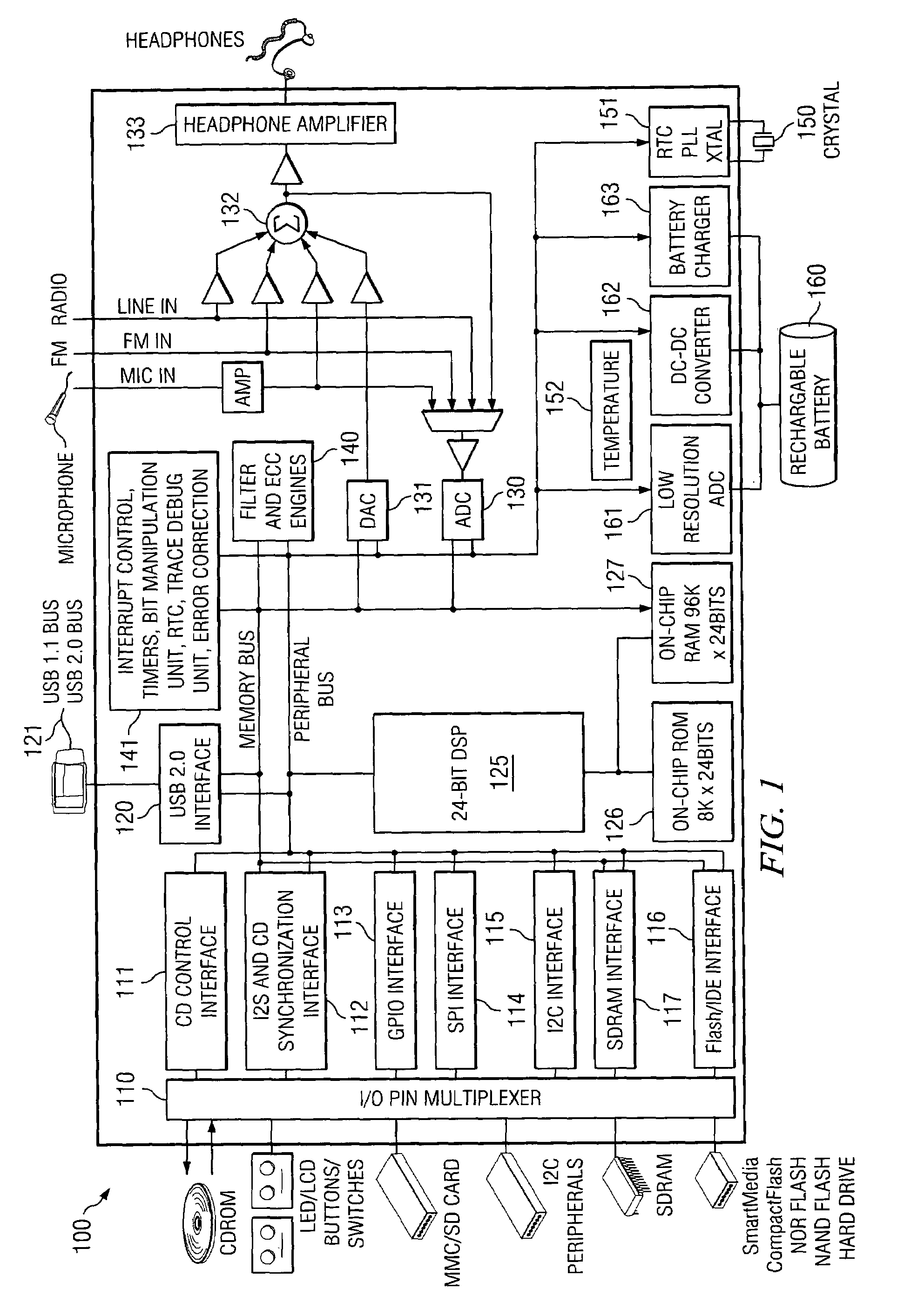
[0023]The embodiments of the present invention may be practiced in a variety of settings that implement a power converter, such as a direct current-direct current (DC-DC) converter. For example, in one embodiment of the invention, a DC-DC converter receives battery power and converts the battery voltage to an output voltage, which is utilized by other component(s) powered by the DC-DC converter. Whenever external power (such as power provided by USB 2.0 interconnection), the DC-DC converter may convert this voltage as well. With that understanding, the examples below are described in reference to converting battery voltage to a DC voltage, which powers a load. Furthermore, although a variety of different systems and components may be implemented, a particular system implementation is illustrated in FIG. 1 as one embodiment of a system to practice the invention.

[0024]Referring to FIG. 1, an example integrated circuit (IC) 100 is shown in which one embodiment of the invention is imple...


PUM


Abstract

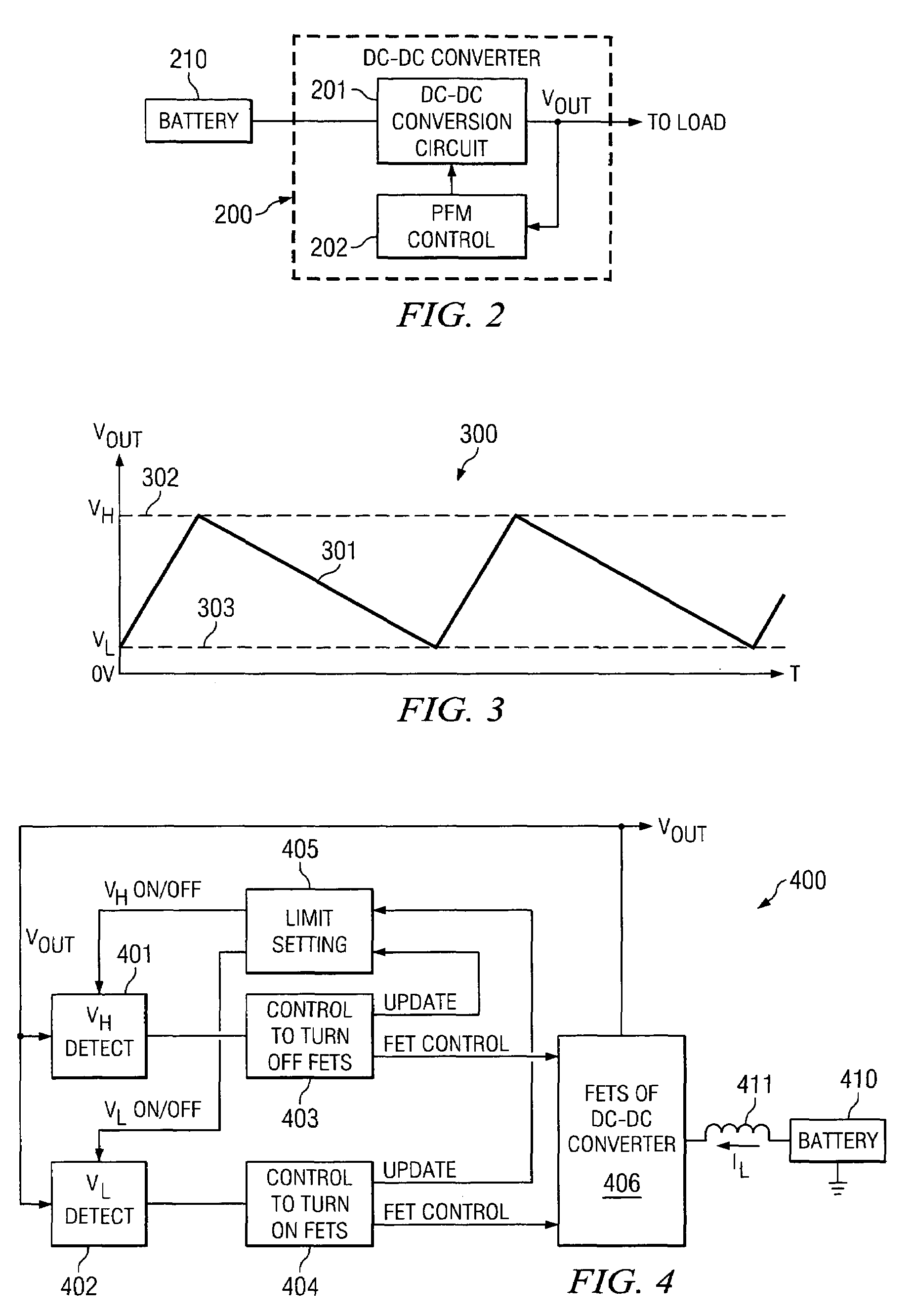
A pulse frequency modulation unit controls upper limit level and lower limit level for an output voltage of a DC-DC converter. A voltage mode control loop uses the upper and lower limit levels in a feedback loop to generate a control signal to enable and disable the converter circuit.

Description

CROSS REFERENCE TO RELATED APPLICATION[0001]This application claims the benefit of U.S. Provisional Patent Application Ser. No. 60 / 484,557; filed Jul. 2, 2003; and titled “Pulse-Skipping PFM DC-DC Converter Using A Voltage Mode Control Loop.”BACKGROUND OF THE INVENTION[0002]1. Technical Field of the Invention[0003]The embodiments of the invention relate to converter circuits and, more particularly, to utilizing a PFM circuit to control a DC-DC converter of an integrated circuit chip.[0004]2. Description of Related Art[0005]A variety of electronic equipment, especially portable or handheld electronic devices, are capable of being powered from a battery. Some of these portable and / or handheld devices include, but are not limited to, laptop or notebook computers, personal digital assistants (PDAs), compact disc (CD) players, digital video disc (DVD) players, MP3 (an audio standard under the Moving Picture Experts Group or MPEG) players, AM / FM (amplitude modulation / frequency modulation)...

Claims


Application Information

Patent Timeline
Patent Type & Authority Patents(United States)
IPC IPC(8): G05F1/40H02M3/158
CPCH02M3/1588H02M1/36Y02B70/16Y02B70/1466H02M2001/0032H02M1/0032Y02B70/10
Inventor MAY, MARCUS W.
Owner NXP USA INC
Learn More