
Selectable multi-performance configuration

a multi-performance configuration and configuration technology, applied in the field of computer graphics, can solve the problems of high-end systems that are typically designed, tested, built as separate products, and generate and display high-quality graphics that are computationally intensive, and achieve the effect of convenient and functional partitioning

Active Publication Date: 2006-07-11
ATI TECH INC
View PDF7 Cites 52 Cited by
  • Summary
  • Abstract
  • Description
  • Claims
  • Application Information

AI Technical Summary

Benefits of technology

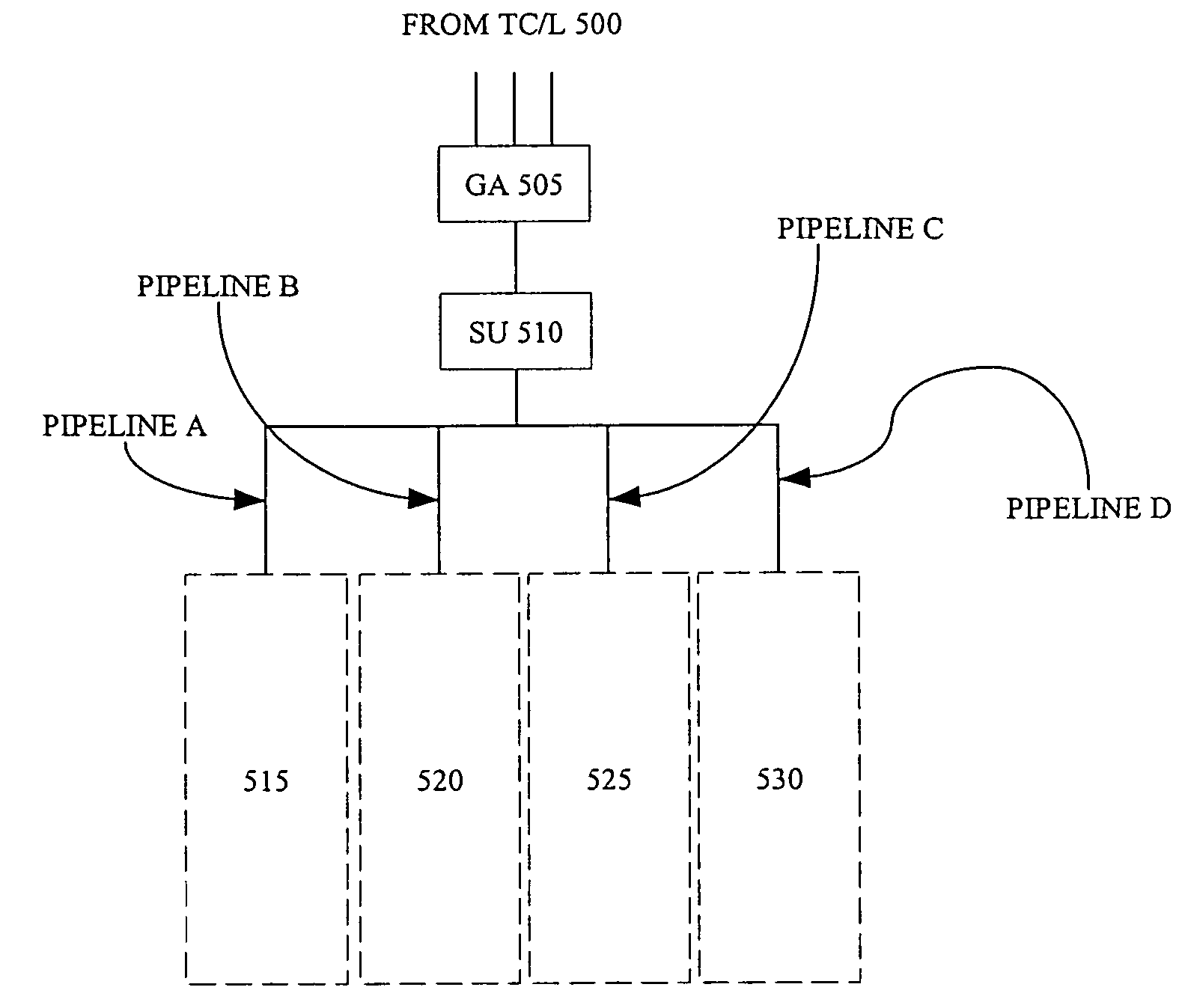
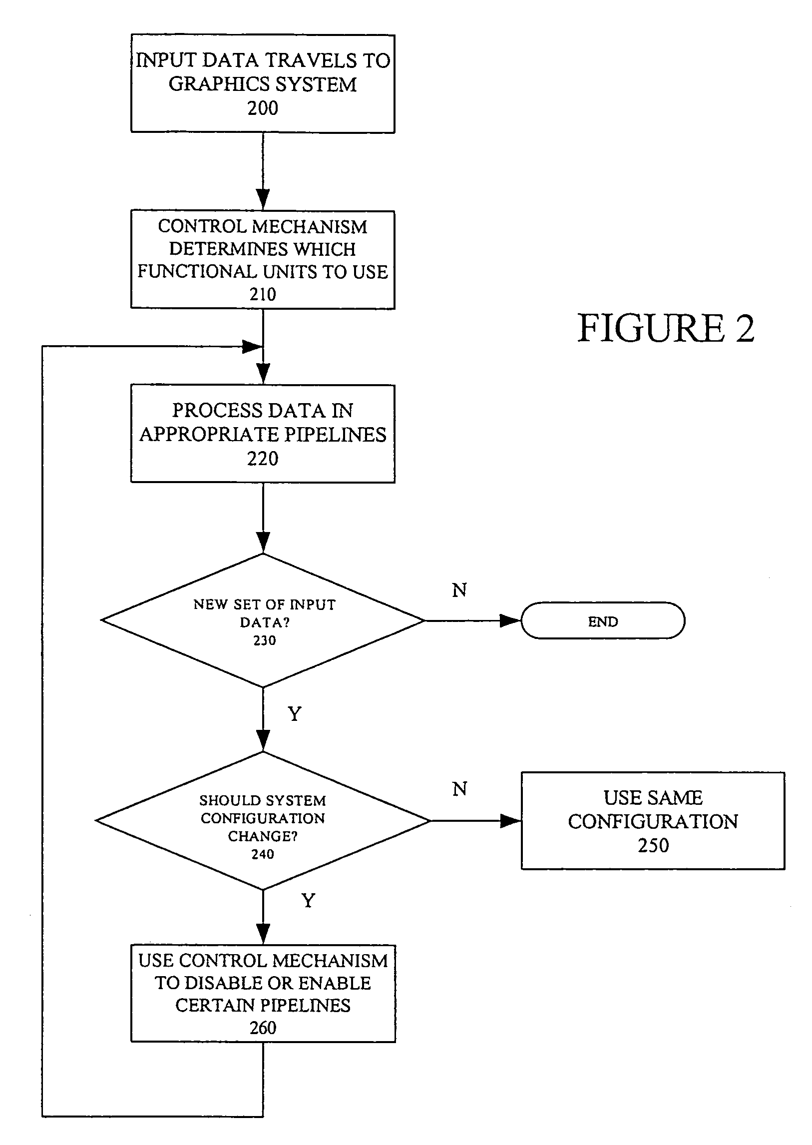
The present invention is a selectable multi-performance configuration that replaces traditional high-end and low-end graphics processing systems with a single unit that can be functionally partitioned. This design reduces the cost associated with designing, testing, and building two distinct types of graphics processing hardware. The unit comprises four partitions that can be used to simulate and test various levels of graphics processing system performances. A control mechanism or mode bit is used to selectively enable and disable the graphics processing pipeline that defines a functional partition. Each pipeline owns one-half, one-quarter, or some other fractional proportion of the screen pixels based on a repeating screen pattern. Allocation of work between the pipelines depends on whether a given pipeline is activate or disabled and also on how each graphics primitive intersects the screen tile pattern.

Problems solved by technology

Generating and displaying high-quality graphics is a computationally intensive undertaking.
High-end systems are more expensive and are designed to provide the highest level of performance for the most rigorous and detailed graphics applications.
One problem associated with high-end and low-end chips is that they are typically designed, tested, and built as separate products.
This is economically disadvantageous from a manufacturer's point of view.
The processes described above in connection with a graphics processing system are computationally intensive.
The computations required by this process would overload the processor and memory of a typical computing system.
High-end systems are more expensive and are designed to provide the highest level of performance for the most rigorous applications.
One problem associated with high-end and low-end systems is that they are typically designed, tested, and built as separate products.
The software and driver development process for these two systems proceeds separately at great expense.
This is economically disadvantageous from a manufacturer's point of view.

Method used


Image

  • Selectable multi-performance configuration
  • Selectable multi-performance configuration
  • Selectable multi-performance configuration

Examples


Embodiment Construction

[0029]The invention relates to a selectable multi-performance configuration. In the following description, numerous specific details are set forth to provide a more thorough description of embodiments of the invention. It will be apparent, however, to one skilled in the art, that the invention may be practiced without these specific details. In other instances, well known features have not been described in detail so as not to obscure the invention.

[0030]Selectable Multi-Performance Configuration

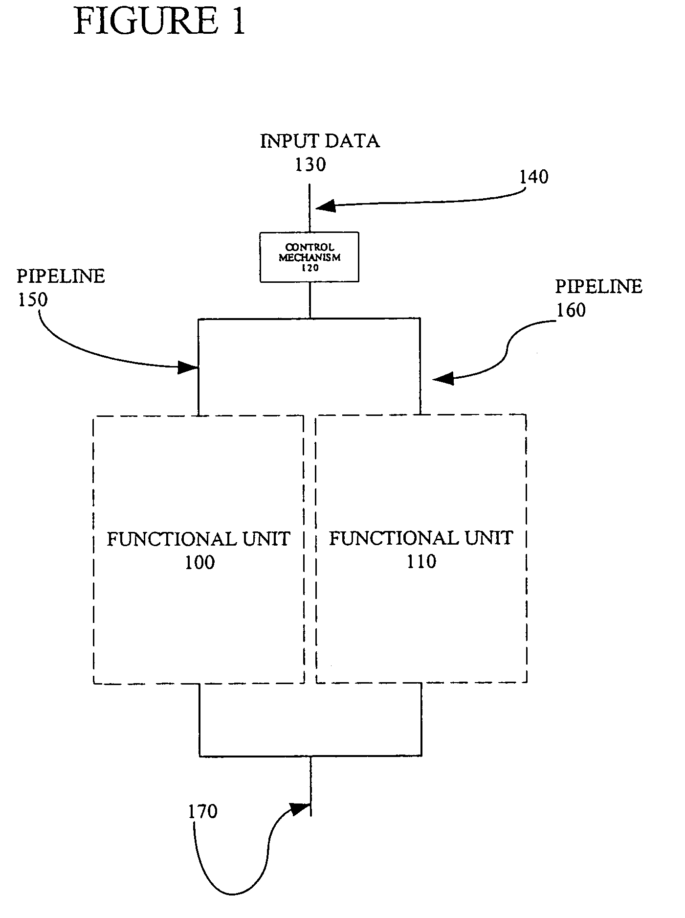
[0031]One embodiment of an architecture used by the present invention is shown in FIG. 1. FIG. 1 contains a first and second functional unit 100 and 110. Each unit is capable of acting as a graphics processing system, such as a rasterizer known to those skilled in the art. A control mechanism 120 is used to instruct either the first functional unit 100 or the second functional unit 110 (or both) to operate. In operation, input data 130 travels along input line 140. The data may travel across...


PUM


Abstract

The present invention relates to a selectable multi-performance configuration. Instead of the traditional methods of producing separate high-end and low-end graphics chips, the present invention produces processing systems in a single unit. The single unit is readily and functionally partitionable. Each partition is capable of independent operation. By using all of the partitions a high-end graphics processing system may be simulated and tested. By using a subset of the partitions, a low-end graphics processing system may be simulated on the same system without the added cost of re-design of either hardware or software.

Description

RELATED APPLICATION[0001]This application is a continuation application of U.S. patent application Ser. No. 10 / 712,578 filed Nov. 12, 2003 now abandoned, which claims priority to U.S. Provisional Patent Application No. 60 / 425,592 filed Nov. 12, 2002.BACKGROUND OF THE INVENTION[0002]1. Field of the Invention[0003]The present invention relates computer graphics. More specifically, one or more embodiments of the present invention relate to a graphics hardware configuration that offers selectable multi-performance.[0004]Portions of the disclosure of this patent document contain material that is subject to copyright protection. The copyright owner has no objection to the facsimile reproduction by anyone of the patent document or the patent disclosure as it appears in the Patent and Trademark Office file or records, but otherwise reserves all copyright rights whatsoever.[0005]2. Background Art[0006]Computer systems are often used to generate and display graphics on an output device such a...

Claims


Application Information

Patent Timeline
Patent Type & Authority Patents(United States)
IPC IPC(8): G06F15/80G06T1/20
CPCG06T15/005G06T2210/52
Inventor LEATHER, MARK M.
Owner ATI TECH INC
Learn More