Use of job interrupt functionality for the production of interrupting and sample job output in digital printing systems

a technology of interrupting and job output, applied in the field of digital printing, can solve the problems of wasting time and material, affecting the quality of digital production printing jobs, and allowing convenient access to printed output, and achieve the effect of reducing costs and avoiding waste of time and material

Inactive Publication Date: 2006-07-11
XEROX CORP
View PDF22 Cites 16 Cited by
  • Summary
  • Abstract
  • Description
  • Claims
  • Application Information

AI Technical Summary

Benefits of technology

[0015]One advantage of the present invention over the prior art is that it allows job quality to be monitored at a minimal cost.
[0016]Another advantage of the present invention is that it allows corrective action to be taken before large amounts of time and material are wasted due to poor print quality.
[0017]Yet another advantage o...

Problems solved by technology

In digital production printing, multi-page documents are being produced and delivered via closed paper paths to finishing devices that do not allow convenient access to printed output until the printing process is complete.
As a result, it is extremely difficult to monitor product quality during a digita...

Method used


Image

  • Use of job interrupt functionality for the production of interrupting and sample job output in digital printing systems
  • Use of job interrupt functionality for the production of interrupting and sample job output in digital printing systems
  • Use of job interrupt functionality for the production of interrupting and sample job output in digital printing systems

Examples


first embodiment

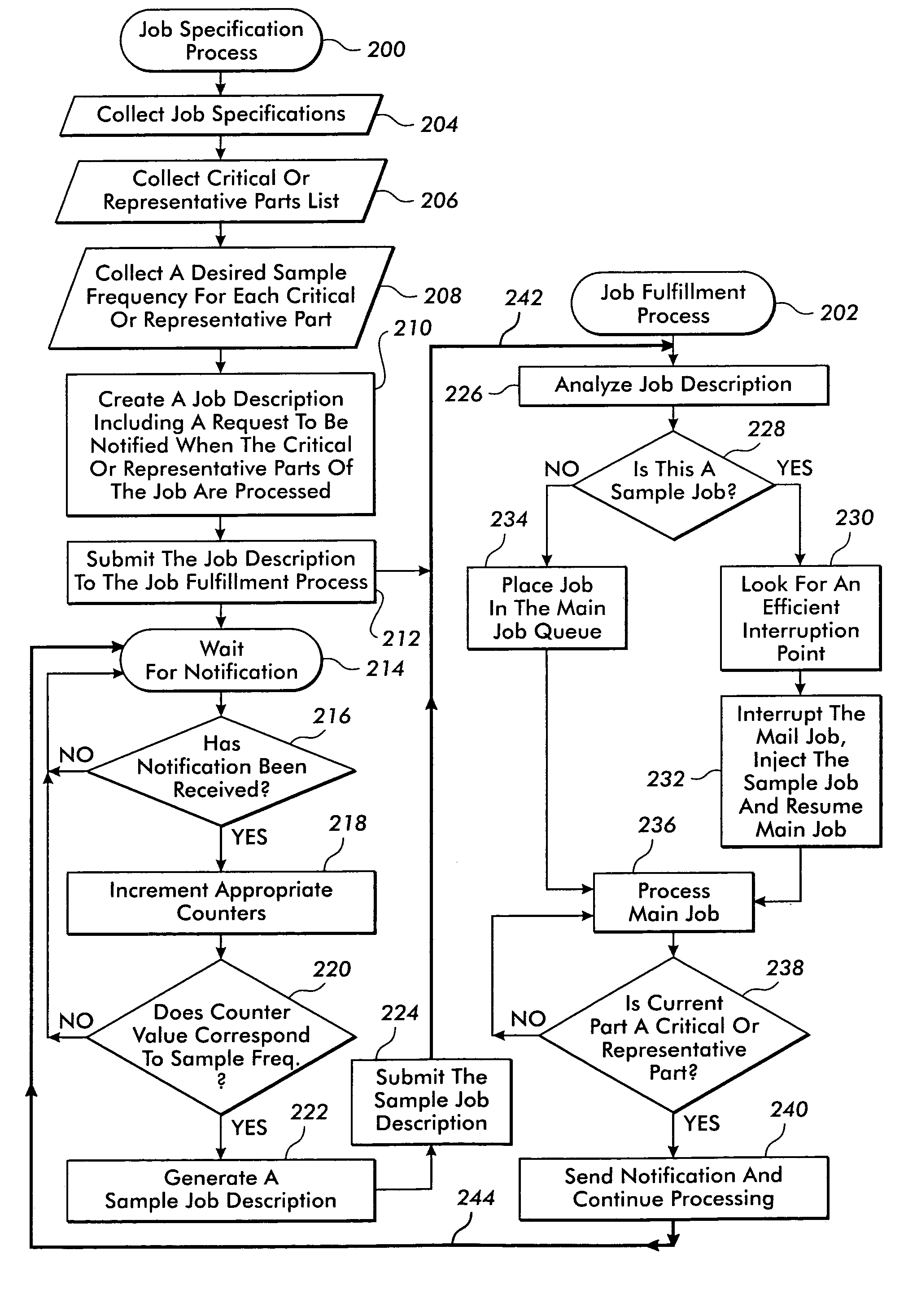
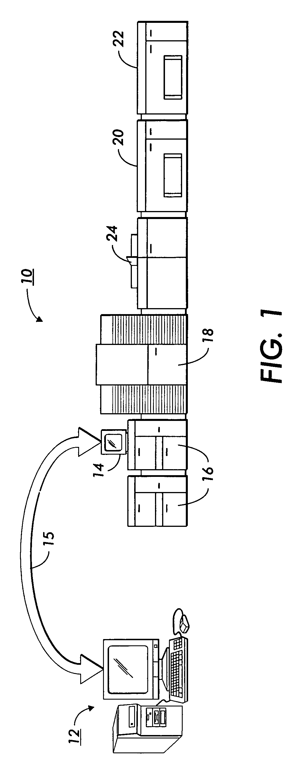
[0029]a method in accordance with the present invention is outlined in FIG. 3. For purposes of illustration, this embodiment has been broken down into two processes, a first job specification process 200 and a first job fulfillment process 202. First job specification process 200 might be run on a digital front end 12 while first job fulfillment process 202 might be run on a mark facility controller 14. However, both processes might also be run on a single computing platform or be further broken down and distributed as tasks for other devices or people to perform.

[0030]First job specification process 200 begins with a collection of job specifications 204. These specifications include the source for the images to be printed, the number of pages to be printed, which if any, are to be printed in color, which if any, are to be printed in high resolution, the size and kind of media on which they are to be printed etc. This information can be provided by the operator via means such as key...

second embodiment

[0042]a method in accordance with the present invention is outlined in FIG. 4. As will be seen, it is similar to that shown in FIG. 3. Similar parts carry the reference designators introduced in FIG. 3.

[0043]Second job specification process 250 includes a step for collecting job specifications 204, a step for collecting 206 a critical or representative parts list and a step for collecting 208 a desired sample interval for each part just as first job specification process 200 does. It has a different job description creation step 254 however. In this embodiment a job description includes the desired critical or representative part sample interval information.

[0044]The job description is submitted 212 to a second job fulfillment process 252. In this embodiment, the second job specification process 250 does not keep track of the number of times each critical or representative part is processed. Instead that task is carried out by the second job fulfillment process 252.

[0045]When notifi...


PUM


Abstract

Main job production progress is monitored so that sample copies of parts of the main job that are designated critical or representative of the job as a whole can be produced on a regular interrupting basis. The samples are used to monitor production quality. Digital printing system modules are arranged and configured to provide a sample job destination separate from the main job destination.

Description

FIELD OF THE PRESENT INVENTION[0001]The invention relates to the art of digital printing. It finds specific application as part of a digital production printing system.BACKGROUND OF THE PRESENT INVENTION[0002]During the printing of long jobs, especially those with color critical output, it is often desirable to view sample copies. Viewing samples allows the press operator to ensure that the appropriate content is being printed and that the appearance of the output matches the customers expectations. When offset presses are used, examining a sample is fairly straightforward. Copies of just one page are being produced at any one time and there are access points in the printing press that allow sheets to be viewed, and in some cases retrieved, during the printing process.[0003]An offset printing press might, for example, have five print units. Each print unit applies one color in a multi-color printing operation. The press is usually open and the quality of the print job can be monitor...

Claims


Application Information

Patent Timeline
IPC IPC(8): H04N1/40
CPCG06F3/1206G06F3/1243G06F3/126G06F3/1284H04N1/00002H04N1/00915H04N1/00031H04N1/00047H04N1/0005H04N1/00063H04N1/00015
Inventor BONIKOWSKI, GREGG A.IGOE, PATRICK T.KIRBY, MICHAEL P.
Owner XEROX CORP
Why Eureka
Try Eureka