Dynamic quality of service monitor

a service monitor and dynamic technology, applied in the field of dynamic quality of service monitors, can solve the problems that the system does not provide for estimating the effects, and achieve the effect of computationally, computationally, computationally and computationally

Inactive Publication Date: 2006-07-11
TELCHEMY
View PDF16 Cites 120 Cited by
  • Summary
  • Abstract
  • Description
  • Claims
  • Application Information

AI Technical Summary

Problems solved by technology

No provision is made in these systems for estimating the effects of the temporal location of impairments on quality.

Method used


Image

  • Dynamic quality of service monitor
  • Dynamic quality of service monitor
  • Dynamic quality of service monitor

Examples


Embodiment Construction

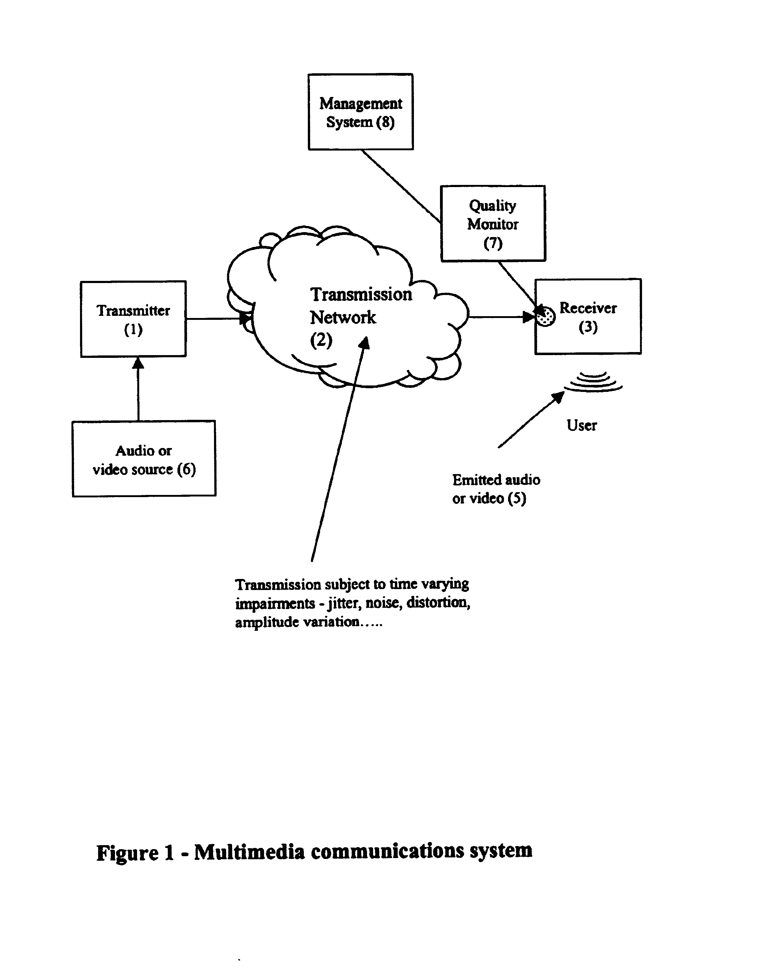
[0032]FIG. 1 shows an example of a multimedia communications system. Audio or video source (6) transmits a stream of audio or video data to user interface (5) by means of transmitter (1), transmission network (2) and receiver (3). Transmission network (2) is subject to time varying impairments which may include jitter, noise, distortion, variations in amplitude and other such impairments. Quality Monitor (7) is connected to or contained within Receiver (3), monitors the received data stream and reports the estimated subjective quality to management system (8).

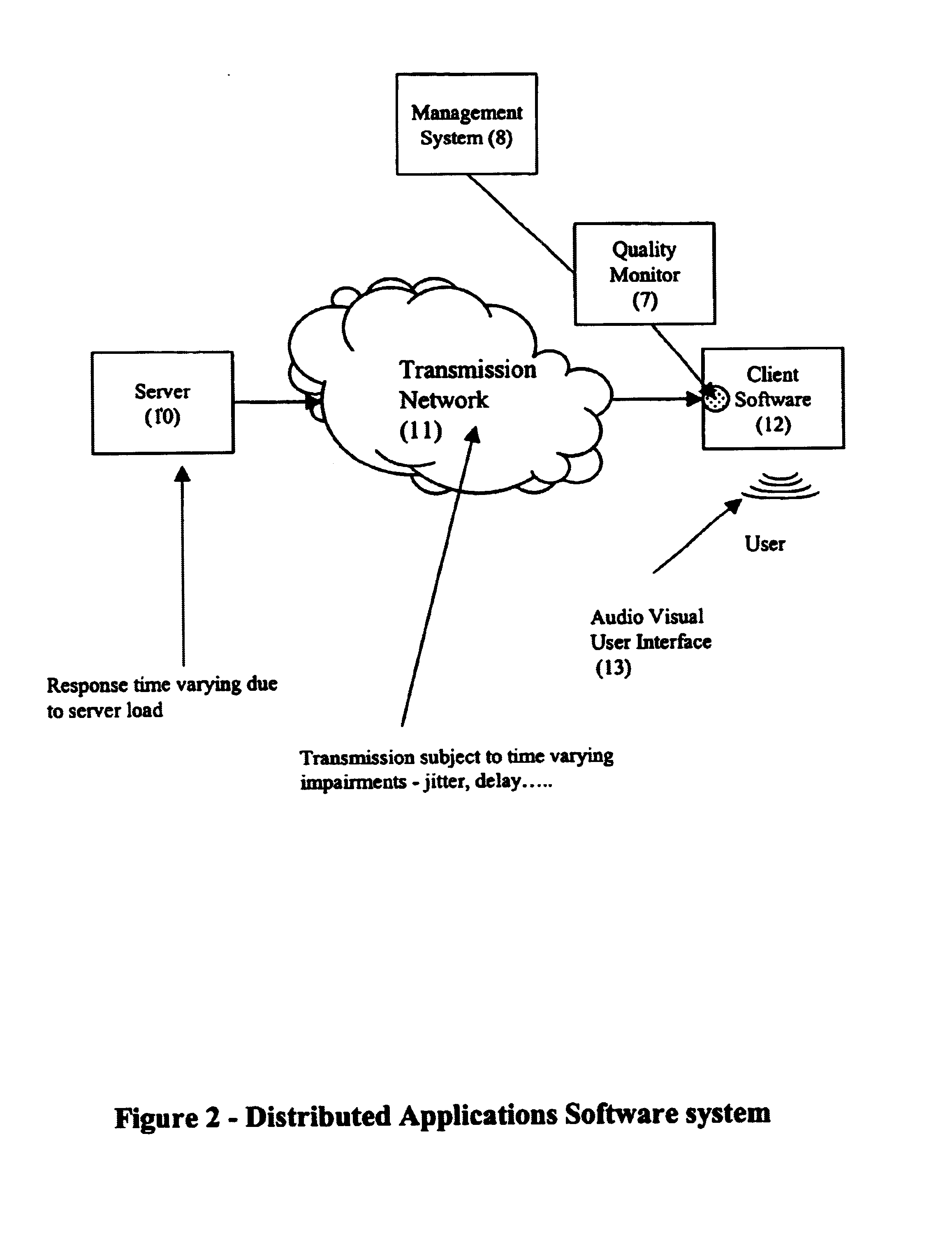
[0033]FIG. 2 shows an example of a distributed applications software system. A user interacts with a remote Server (10) by means of User Interface (13), Client Software (12) and Transmission Network (11). Requests from the user for data are submitted via User Interface (13) to Client Software (12). Client Software (12) forwards a representation of the user request through Transmission Network (11) to Server (10). Server (10) se...


PUM


Abstract

A subjective quality monitoring system for multimedia signal transmission systems or distributed applications software systems employs a counter which is increased if subjective quality is high and decreased if subjective quality is low in order to represent the effects of the relative temporal location of transmission impairments or system loading.

Description

RELATED PATENT APPLICATION[0001]The present invention describes an alternative and extended means of monitoring certain time related aspects of quality of service to co-pending patent application Ser. No. 09 / 551,498 filed on 18th Apr. 2000.BACKGROUND-FIELD OF INVENTION[0002]This invention relates to methods of estimating the subjective quality of a multimedia communications system or distributed applications software system in which the quality of the received audio, voice, video or the response time of the software system may be degraded by time varying impairments and in which it is accordingly desirable to have some means of measuring or estimating the subjective or perceptual quality of the decoded audio, voice, video or software system.[0003]It is desirable to have some means of measuring the quality of a distributed system in order that it can be verified that the system is operating correctly and that user expectations are being met. In the case of a speech transmission syste...

Claims


Application Information

Patent Timeline
Patent Type & Authority Patents(United States)
IPC IPC(8): H04B17/00
CPCH04B17/00H04B17/309H04L12/2602H04L12/2697H04L41/147H04L43/00H04L43/50H04L1/20H04L41/5067H04L41/5087H04L41/509H04L43/0852H04L43/087H04L43/16H04W24/00
Inventor CLARK, ALAN DOUGLAS
Owner TELCHEMY
Why Eureka
Try Eureka