Heart rate monitor

a monitor and heart rate technology, applied in the field of heart rate monitors, can solve the problems of serious problems in the readability of the display, the inability to properly interpret the position of the moving indicator with respect to the display elements indicating the minimum, etc., and achieve the effect of safe exercise and fast and easy readability

Inactive Publication Date: 2006-07-11
POLAR ELECTRO
View PDF10 Cites 79 Cited by
  • Summary
  • Abstract
  • Description
  • Claims
  • Application Information

AI Technical Summary

Benefits of technology

[0008]An advantage of the invention is fast and easy readability enabling the user to observe and thus control his or her workout in a more reliable manner. In addition, exercising becomes safer since the user is provided with an overall picture of the height of his or her current heart rate level with respect to the minimum and the maximum limit of a desired heart rate level.
is fast and easy readability enabling the user to observe and thus control his or her workout in a more reliable manner. In addition, exercising becomes safer since the user is provided with an overall picture of the height of his or her current heart rate level with respect to the minimum and the maximum limit of a desired heart rate level.

Problems solved by technology

Both extreme ends of the movement range are provided with borderlines generated by additional display segments producing a crosswise line, so the user has to interpret the location of a moving indicator with respect to the borderlines, thus being unable to properly interpret the location of the moving indicator with respect to the display elements indicating the minimum and the maximum limit of a desired heart rate level.
The above-described known solution causes serious problems to the readability of the display, particularly when the user glances quickly at the display or when there is some kind of movement between a viewer's eye and the heart rate monitor, which is usually the case while walking or running or the like, when the heart rate monitor is kept in the user's moving hand or e.g. attached to the hand-bar e.g. during a cycling exercise.

Method used


Image

  • Heart rate monitor
  • Heart rate monitor
  • Heart rate monitor

Examples


Embodiment Construction

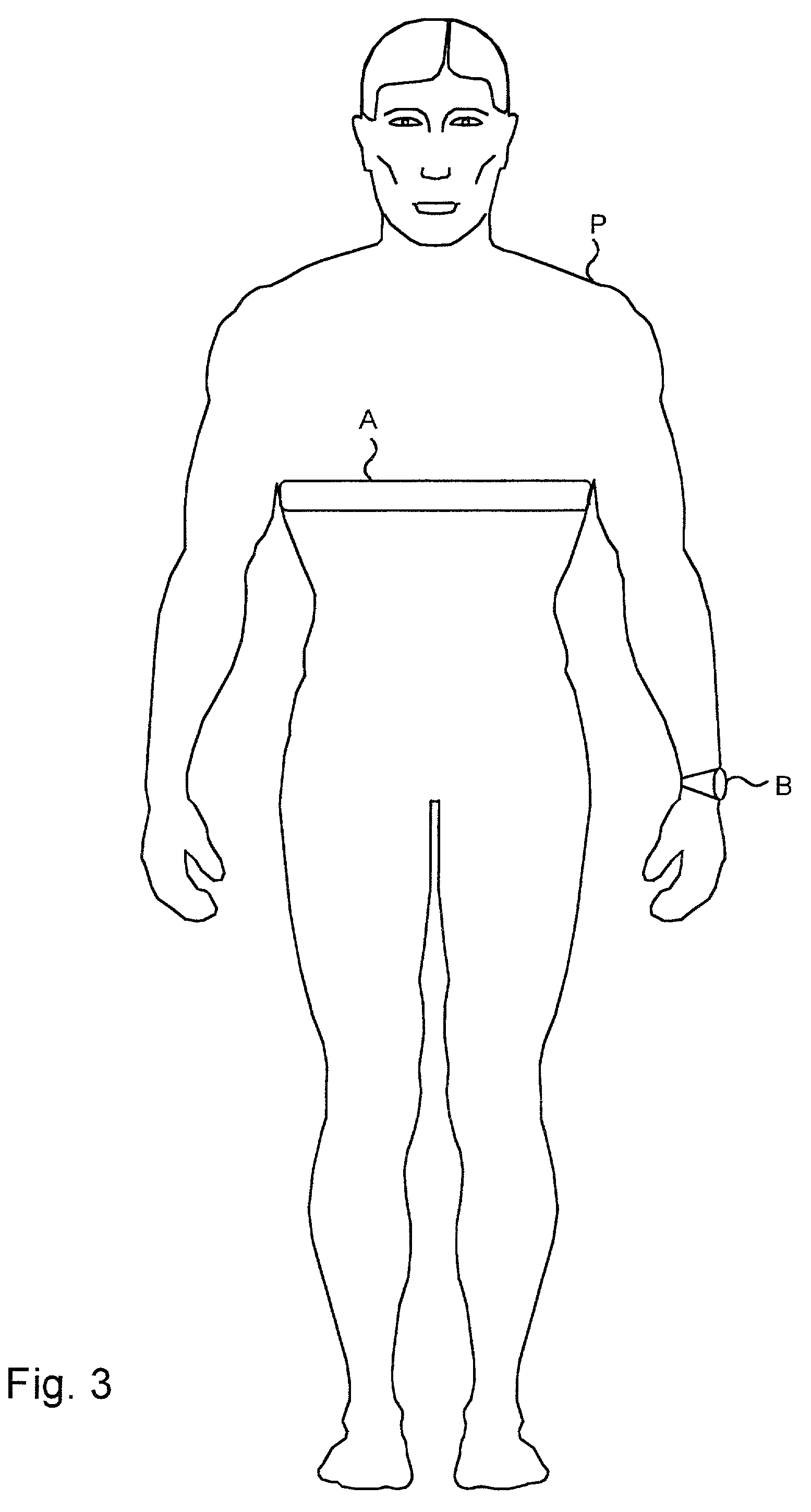
[0016]The invention thus relates to a carry-on heart rate monitor measuring a person's heart rate non-invasively, i.e. from outside a body, i.e. in practice on the skin of a person.

[0017]The general operation and structure of a hear rate monitor will be discussed first.

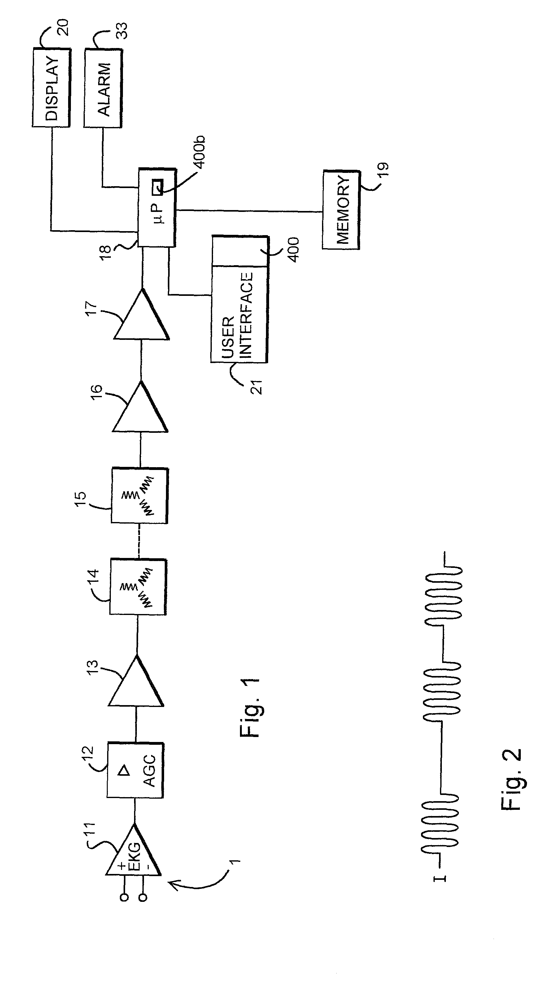
[0018]FIG. 1 shows a telemetric device for measuring the heart rate, i.e. a heart rate measurement arrangement, which comprises electrodes 1, an ECG preamplifier 11 equipped with differential input poles, an amplifier 12, such as an AGC amplifier, a power amplifier 13, a coil structure 14, 15, a preamplifier 16, a signal amplifier 17, a data-processing unit 18, such as a microcomputer, a memory unit 19 and a display 20, such as a liquid crystal display. In FIG. 1, the electrodes 1 of the telemetric heart rate measurement device are connected to the differential input poles of the ECG preamplifier. A heart rate signal supplied by the preamplifier 11 is amplified in the amplifier 12, e.g. an AGC amplifier, which control...


PUM


Abstract

The invention relates to a heart rate monitor. The essential point of the invention is that a display element (201) of a display (20) of the heart rate monitor for displaying a settable minimum limit for a heart rate level is located at a first end (211) of a display element unit (210) controlled according to the heart rate level, on the same side of the display as the first end of the display element unit. Similarly, a display element (202) for displaying a settable maximum limit for a heart rate level is located at a second end (220) of the display element unit (210), on the same side of the display as the second end of the display element unit.

Description

BRIEF DESCRIPTION OF THE RELATED ART[0001]The invention relates to heart rate monitors. The invention is applied to a personal non-invasive heart rate monitor. The heart rate monitor equipment may consist e.g. of a conventional two-part device comprising a heart rate transmitter, usually of the transmitter belt type, comprising ECG electrodes, and a wristband receiver unit having a telemetric, inductive or optical connection to the heart rate transmitter and comprising e.g. a microprocessor, display and a user interface. Alternatively, the equipment can be a heart rate measurement apparatus which constitutes one integrated whole, particularly a single wristband, in which case the wristband also comprises a sensor, such as ECG electrodes or a pressure sensor, in addition to the other parts. The sensor may even be an optical heart rate measurement sensor.[0002]Heart rate monitors employ a heart rate limit alarm to direct a user's workout such that the exerciser is given an alarm if th...

Claims


Application Information

Patent Timeline
Patent Type & Authority Patents(United States)
IPC IPC(8): A61B5/04A61B5/0245
CPCA61B5/02455
Inventor PULKKINEN, IIRISKIURU, EEVALAHDESMAKI, TAPANI
Owner POLAR ELECTRO
Why Eureka
Try Eureka