Detachable gun barrel assembly

Active Publication Date: 2006-07-18
RUSTICK JOSEPH M
View PDF16 Cites 54 Cited by
  • Summary
  • Abstract
  • Description
  • Claims
  • Application Information

AI Technical Summary

Benefits of technology

[0009]The elongated section of the detachable barrel is dimensioned with an outside diameter which forms an external shoulder at the juncture of the securing section and the elongated section. The external shoulder contacts the receiving end section upon affixation of the detachable barrel to the adapter. When the barrel is completely attached, the alignment section contacts the limit flange, the securing section contacts the internal flange of the receiving end section and the external shoulder of the barrel is in contact with the receiving end section to provide three registration surfaces or limiting stops. The surfaces are orthogonal to the axis of the detachable barrel assembly. As a result, the wear surfaces of the contact areas of the assembly are comprised of the square thread surfaces and the three limiting stops. No angled surface is utilized in the assembly. As a result, wear through repeated detachment of the barrel from the adapter receiver does not result in angular displacement of the elongated barrel with respect to the receiver of the weapon. Consequently, accuracy is maintained over periods of repeated use with different barrels. The adapter once affixed to the receiver need not be removed in normal operating conditions.

Problems solved by technology

In addition, the rifling in a weapon barrel is known to wear as a result of repeated use often requiring replacement.
The use of vee-threads and chamfered surfaces is likely to result in uneven wearing during repeated use.
As a result, the accuracy of the weapon degrades as the worn surfaces of the angled parts of the attachment structure allow relative movement therebetween.
Again, uneven wearing of angled surfaces over a period of time can result in a reduction in accuracy of the weapon.

Method used


Image

  • Detachable gun barrel assembly
  • Detachable gun barrel assembly

Examples


Embodiment Construction

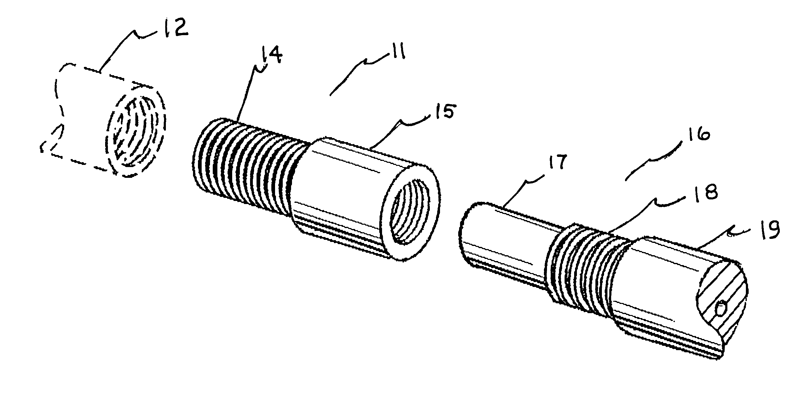
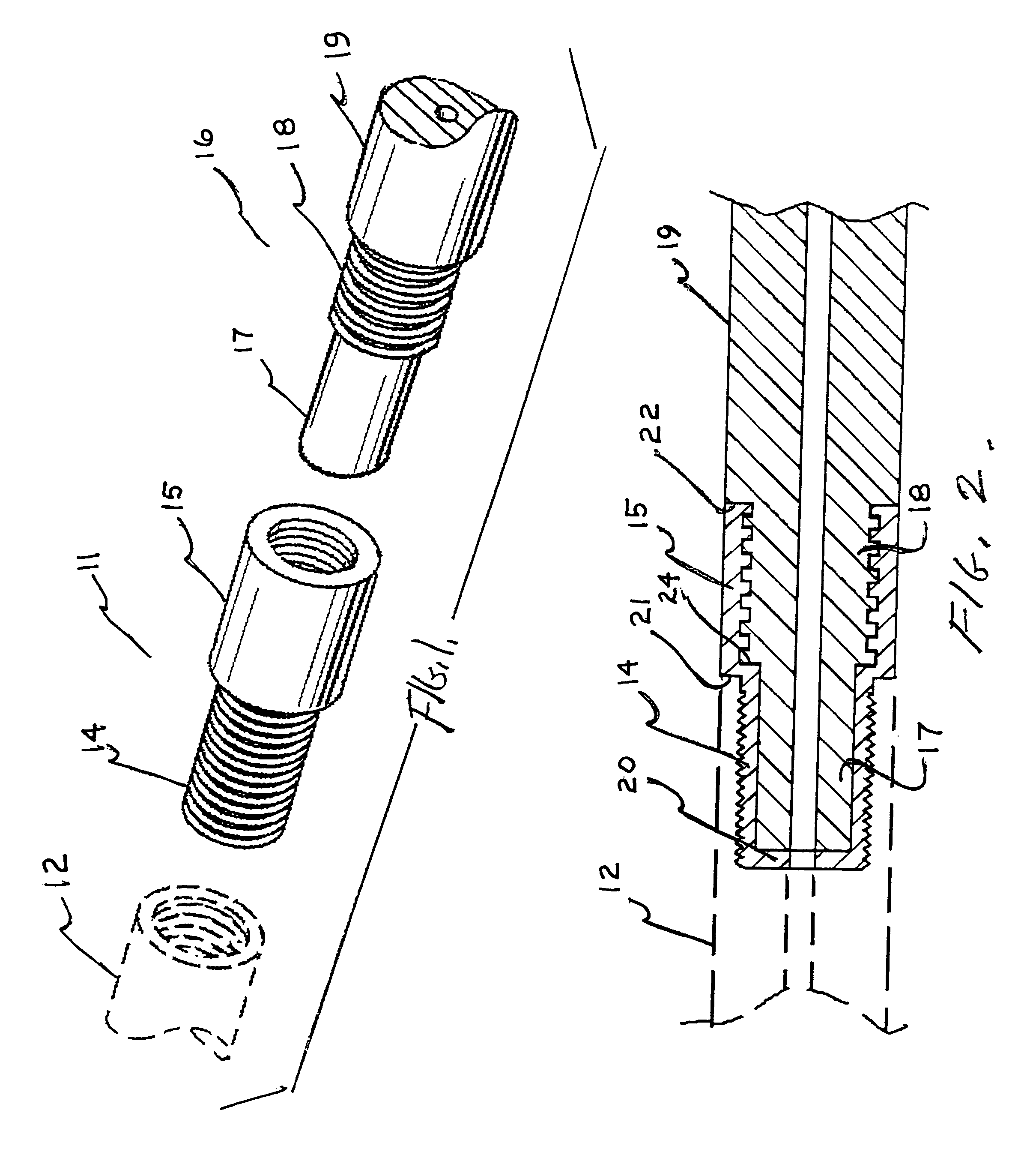
[0013]Referring now to FIG. 1, the detachable gun barrel assembly which is the subject of the present invention is shown comprising an adapter 11 dimensioned for attachment to receiver 12 shown in dashed outline. The receiver is an integral part of the weapon and is typically provided with internal vee-threads for receiving a detachable barrel. In the subject invention, the adapter 11 is provided with a mating end section 14 having vee-threads. However, the adapter may be made integral with the receiver if desired. In this case, the external threads of the adapter are not necessary. The adapter also includes a receiving end section 15 of larger internal and external diameters. The receiving end section of the adapter is provided with a square internal thread for engagement with a mating external thread on the detachable barrel. In use, the adapter remains attached to the receiver and the barrel is detached for weapon storage or transport. However, the adapter is capable of removal i...


PUM


Abstract

A detachable gun barrel assembly having an adapter for threaded engagement with the receiver and a barrel dimensioned for affixation to the adapter. The adapter has a mating end section which threadedly engages the receiver V-threads and a receiving end section having square internal threads. The mating end section has a limit flange at its innermost end. The receiving end section has a larger internal diameter to form an internal flange or stop between sections. The barrel has an alignment section which inserts into the mating end section and contacts the limit flange. A securing section of the barrel is provided with a square external thread to engage the receiving end section and contact the internal flange. The elongated barrel is provided with an external shoulder which contacts the receiving end section upon affixation of barrel to adapter thereby providing a number of stops to maintain barrel alignment.

Description

CROSS REFERENCE TO RELATED APPLICATION[0001]The present application is based on provisional patent application Ser. No. 60 / 387,157 filed Jun. 6, 2002.BACKGROUND OF THE INVENTION[0002]This invention relates to the provision of a detachable gun barrel assembly for a weapon wherein the accuracy of the weapon is maintained during repeated cycles of detachment and reattachment.[0003]The novel assembly includes an adapter for affixation to the receiver of the weapon to enable the detachable barrel of the invention to be used with existing weapons. More particularly, the present invention is directed to the combination of the adapter and a detachable gun barrel having at one end at least three regions of differing diameters. Square threads are located on an intermediate region of the barrel end for attachment to the adapter. The adapter is comprised of two parts: first, a mating end section which is provided with vee-threads to interengage with the receiver and, second, a receiving end sec...

Claims


Application Information

Patent Timeline
IPC IPC(8): F41A21/00
CPCF41A21/482
Inventor RUSTICK, JOSEPH M.
Owner RUSTICK JOSEPH M
Why Eureka
Try Eureka