Module connector

a module and connector technology, applied in the direction of coupling device connection, television system, engagement/disengagement of coupling parts, etc., can solve the problems of cumbersome operation and easy damage to the modul

Inactive Publication Date: 2006-07-18
CHENG UEI PRECISION IND CO LTD
View PDF7 Cites 33 Cited by
  • Summary
  • Abstract
  • Description
  • Claims
  • Application Information

AI Technical Summary

Benefits of technology

[0008]An object of the present invention is to provide a module connector comprising a housing having four sidewalls that define a chamber for receiving a module therein. Each sidewall defines a plurality of contact recesses. A plurality of contacts is accommodated in the contact recesses and electrically contact with the module. A pivotal cover has a top pressing cover, at least a pivotal arm and at least a locking claw extending downwardly from the top pressing cover. The pivotal arm pivotally mounts the pivotal cover on the housing to enable the pivotal cover to pivot between an open position to enable the module to be inserted in the chamber and a closed position with the top pressing cover pressing downwardly on the top of the module to prevent the module from being pulled out. The locking claw latches the pivotal cover in the closed position. Pivoting the pivotal cover to the open position, the module can be pulled out. So no special tool is required. Furthermore, the contacting area between the top pressing cover and the module is enlarged to provide enough force to prop against the module thereby retaining the module in the module connector reliably.

Problems solved by technology

However, when the digital camera lens module is needed to be pulled out from the module connector, a special tool for pushing the pull-out prevention pieces aside is required, which makes it cumbersome to operate and is easy to damage the module.

Method used


Image

  • Module connector
  • Module connector
  • Module connector

Examples


Embodiment Construction

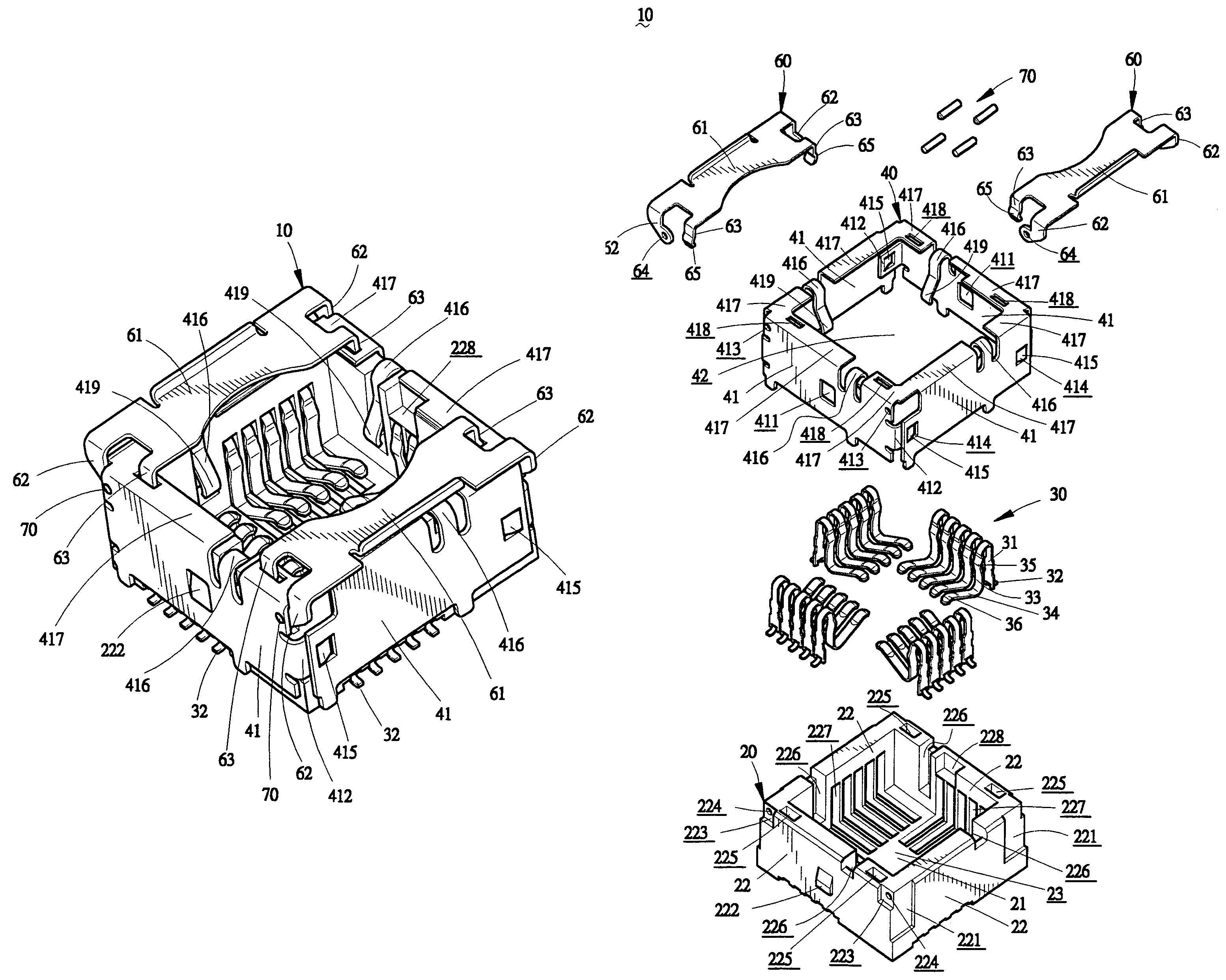
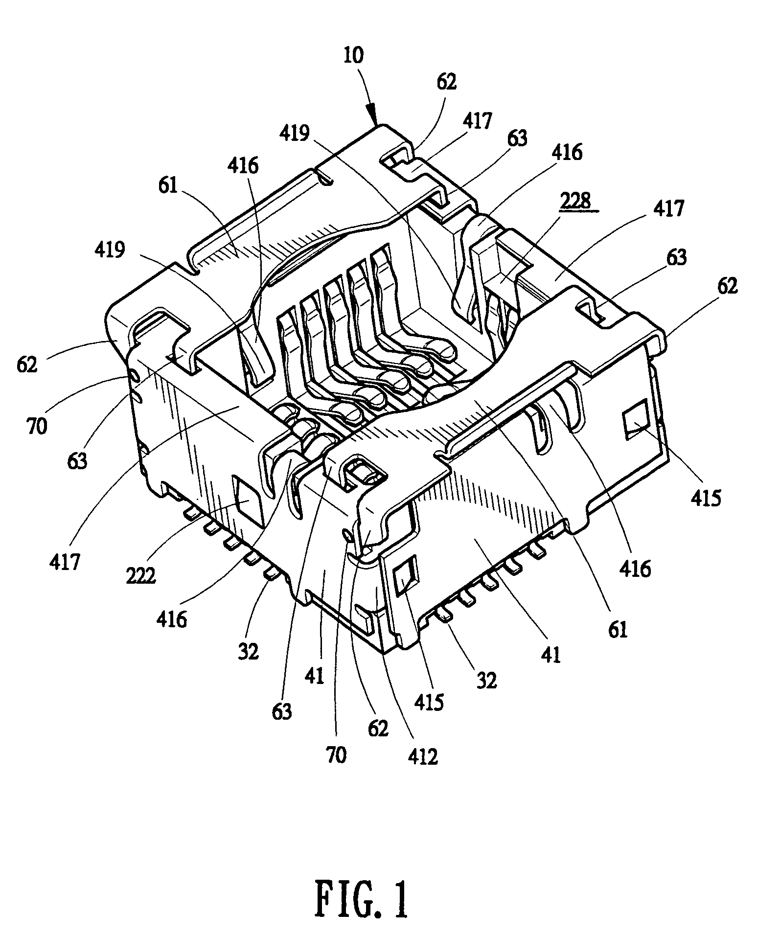
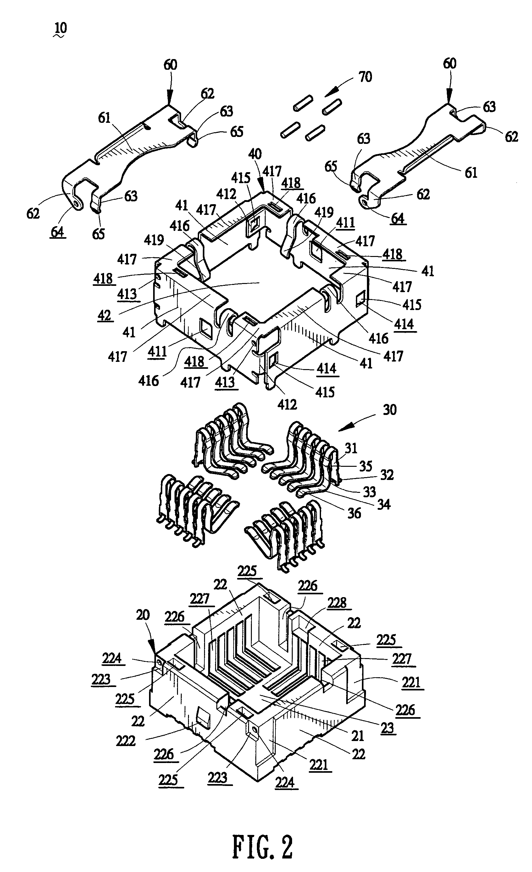
[0021]Now, referring to the drawings in greater detail, and first to FIGS. 1 and 2, the module connector 10 of the present invention includes a housing 20 receiving a plurality of contacts 30 therein, a shell 40 wrapping the housing 20, and a pivotal cover 60 pivotally mounted on the housing 20 by several positioning studs 70.

[0022]The housing 20 includes a bottom board 21 and four sidewalls 22 extending perpendicularly and upwardly from four edges of the bottom board 21 to define an upwardly-open chamber 23. Embedding recesses 221 are defined in outer sides of the left and the opposite right sidewalls 22. The front sidewall 22 and the opposite rear sidewall 22 respectively have an engagement protrusion 222 projected outwardly on about the middle portions of the outer sides thereof, two engagement-rotating recesses 223 in the upper corners of the outer sides thereof, and two stud-receiving holes 224 communicating with the corresponding engagement-rotating recesses 223 and open to ou...


PUM


Abstract

The present invention provides a module connector including a housing having four sidewalls that define a chamber for receiving a module therein. Each sidewall defines a plurality of contact recesses. A plurality of contacts is accommodated in the contact recesses and electrically contact with the module. A pivotal cover has a top pressing cover, at least a pivotal arm and at least a locking claw extending downwardly from the top pressing cover. The pivotal arm pivotally mounts the pivotal cover on the housing to enable the pivotal cover to pivot between an open position to enable the module to be inserted in the chamber and a closed position with the top pressing cover pressing downwardly on the top of the module to prevent the module from being pulled out. The locking claw latches the pivotal cover in the closed position.

Description

BACKGROUND OF THE INVENTION[0001]1. Field of the Invention[0002]The present invention relates to a module connector, especially to a module connector to retain a digital camera lens module.[0003]2. The Related Art[0004]Nowadays, digital photographing technology is widely used in people's daily life. More and more electronic devices are desired to integrate photographing function thereon. To integrate the photographing function, a digital camera lens module must be assembled to the electronic device. The most common solution to assemble the module is to provide a module connector in the electronic device for fitting the module therein.[0005]Japan patent application No. 2004-241225 published on Aug. 26, 2004 discloses a module connector for a digital camera lens module. The module connector includes a square box-like housing with four sidewalls surrounding a chamber to accommodate the digital camera lens module. Each sidewall holds a plurality of contacts in its inner surface. Each co...

Claims


Application Information

Patent Timeline
Patent Type & Authority Patents(United States)
IPC IPC(8): H01R13/62
CPCH01R12/7076H04N5/2253H01R13/62966H04N23/54
Inventor WANG, CHIN CHOUKAO, YI CHIUHUANG, CHUNG HSIN
Owner CHENG UEI PRECISION IND CO LTD
Why Eureka
Try Eureka