Connector which can easily be mounted to an object and provided with EMI protection

a technology of connecting rods and connectors, which is applied in the direction of coupling device connections, coupling protective earth/shielding arrangements, aperture leaage reduction, etc., can solve the problems of troublesome fixing operation, generating undesired radiation, and difficult to bring the receptacle connector, the panel, and the retainer clip into tight contact with one another

Inactive Publication Date: 2006-07-18
JAPAN AVIATION ELECTRONICS IND LTD
View PDF8 Cites 21 Cited by
  • Summary
  • Abstract
  • Description
  • Claims
  • Application Information

AI Technical Summary

Benefits of technology

[0006]It is therefore an object of this invention to provide a connector which can easily be mounted to an object such as a panel and which is provided with EMI protection.
[0008]According to an aspect of the present invention, there is provided a connector which comprises a connector element to be connected to a mating connector in a predetermined direction and a ring-shaped guide member engaged with the connector element in the predetermined direction to receive the mating connector, the guide member having a spring portion which is formed on its inner surface and is adapted to be pressed by the mating connector in a radially outward direction, the spring portion serving to stabilize the mating connector.

Problems solved by technology

However, a space for a screw structure is required and a fixing operation is troublesome.
Therefore, it is difficult to bring the receptacle connector, the panel, and the retainer clip into tight contact with one another.
Thus, presence of the gap may possibly result in generation of undesired radiation due to leakage of electromagnetic waves from the electronic apparatus.
Further, a noise may possibly enter into the electronic apparatus to cause operation error of the electronic apparatus.
Thus, there is a problem of electromagnetic interference (EMI).

Method used


Image

  • Connector which can easily be mounted to an object and provided with EMI protection
  • Connector which can easily be mounted to an object and provided with EMI protection
  • Connector which can easily be mounted to an object and provided with EMI protection

Examples


first embodiment

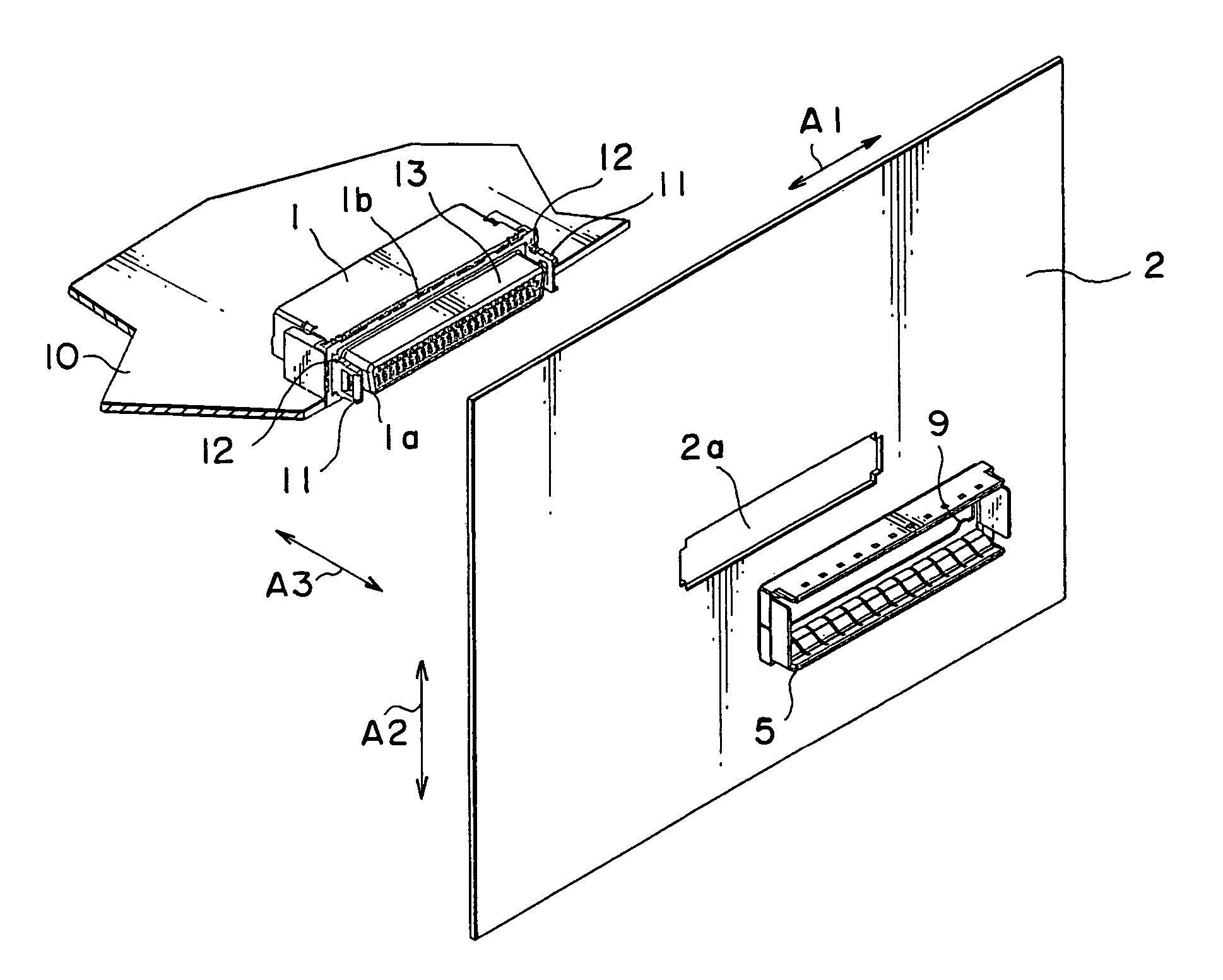
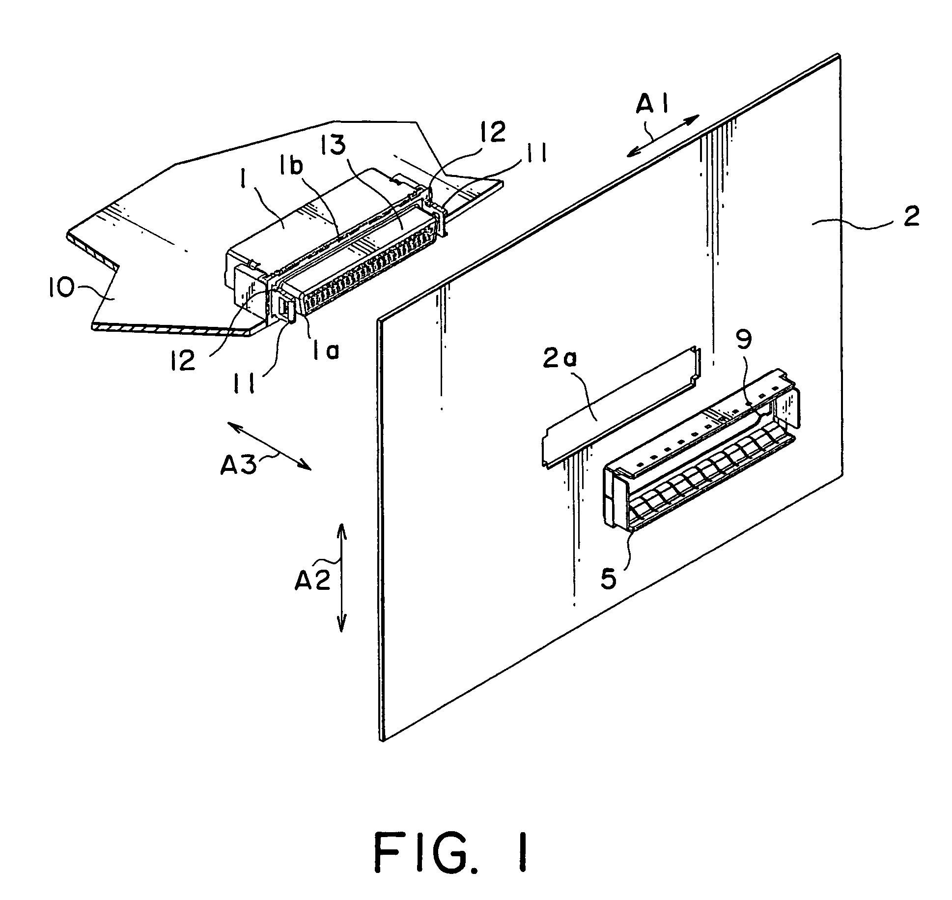
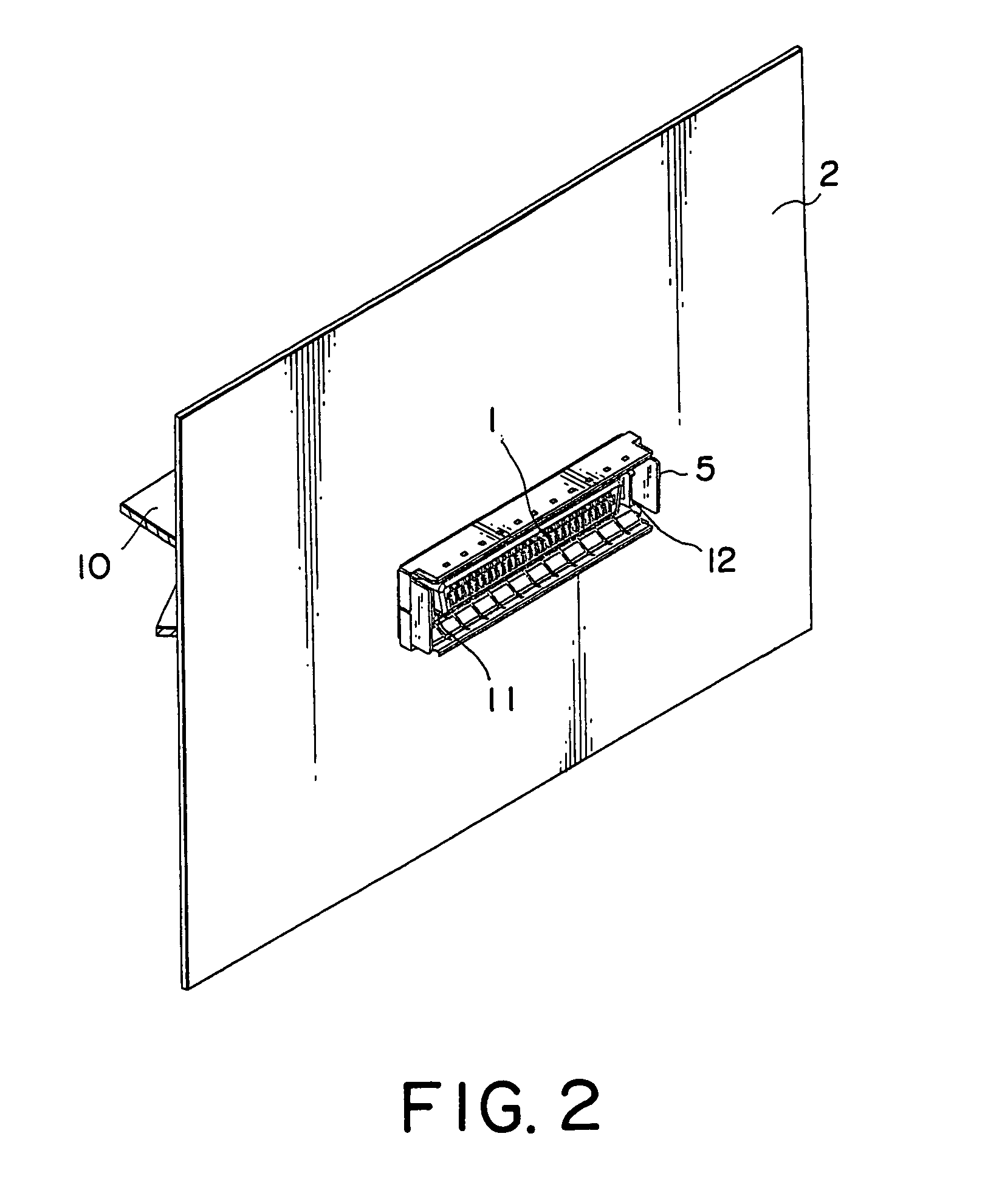
[0024]Referring to FIGS. 1 and 2, description will be made of a connector according to this invention.

[0025]The connector illustrated in the figures is adapted to be mounted to a panel 2 of an electronic apparatus and is herein called a first connector. The first connector comprises a connector element 1 having a plurality of conductive contacts (not shown) and a guide member 5 having a rectangular ring shape. The connector element 1 is mounted to an edge portion of a printed circuit board 10 to be placed on a rear side of the panel 2. The guide member 5 is placed on a front side of the panel 2.

[0026]The connector element 1 has a connecting end portion 1a having a rectangular section defined by a conductive shell member 13, and two fixing plates 11 disposed at opposite ends of the connecting end portion 1a in a transversal direction (i.e., a first direction A1), respectively. Each of the fixing plates 11 is provided with a pair of engaging recesses 12 formed symmetrical in a vertica...

second embodiment

[0037]Referring to FIGS. 7 to 9, 11A, and 11B, description will be made of a connector according to this invention. Similar parts are designated by like reference numerals and description thereof will be omitted.

[0038]The connector illustrated in the figures further comprises a frame-like structure member covering an entire circumference of the guide member 5. The frame-like structure member 7 covers the guide member 5 so as to simultaneously surround the connecting portion between the connector element 1 and the second connector 6. The frame-like structure member 7 made of metal exhibits a shielding function against electromagnetic radiation from both outside and inside of the area around the connecting portion between the connector element 1 and the second connector 6. Further, the frame-like structure member 7 serves to mechanically protect the area around the connecting portion between the connector element 1 and the second connector 6.

[0039]When the second connector 6 is fitted...


PUM


Abstract

In a connector including a connector element to be connected to a mating connector in a predetermined direction, a ring-shaped guide member is engaged with the connector element in the predetermined direction to receive the mating connector. The guide member has a spring portion which is formed on its inner surface and is adapted to be pressed by the mating connector in a radially outward direction. The spring portion serves to stabilize the mating connector.

Description

[0001]This application claims priority to prior Japanese patent application JP 2004-98649, the disclosure of which is incorporated herein by reference.BACKGROUND OF THE INVENTION[0002]This invention relates to a connector adapted to be mounted to an object such as a panel of a housing or casing.[0003]In a connector of this type, a receptacle connector is generally fixed to a panel by fastening and tightening a screw. Such technique is adopted in most input / output (I / O) connectors for computers. However, a space for a screw structure is required and a fixing operation is troublesome.[0004]In U.S. Pat. No. 6,513,206, it is proposed to fix a receptacle connector to a panel of an electronic apparatus by the use of a retainer clip.[0005]In the technique proposed in the above-mentioned United States Patent, a gap must be formed between the receptacle connector and the panel in order to insert the retainer clip. Therefore, it is difficult to bring the receptacle connector, the panel, and t...

Claims


Application Information

Patent Timeline
Patent Type & Authority Patents(United States)
IPC IPC(8): H01R13/73H02B1/01H01R13/648H01R13/627H01R13/658H01R13/6582H01R13/74H05K9/00
CPCH01R13/65802H05K9/0018H01R13/745Y10S439/939H01R13/6582
Inventor HAGA, GOROKOTAKA, KENICHI
Owner JAPAN AVIATION ELECTRONICS IND LTD
Why Eureka
Try Eureka