Vertebral interbody cage with translatable locking screw

a technology of locking screw and vertebrae, which is applied in the field of vertebral interbody cage with translatable locking screw, can solve the problems of disc loss, loss of normal spinal curvature or proper alignment of vertebrae, and loss of disc shape, so as to achieve the effect of reducing the risk of disc loss, and reducing the normal spinal curvature of the spin

Inactive Publication Date: 2006-07-18
ZIMMER BIOMET SPINE INC
View PDF26 Cites 356 Cited by
  • Summary
  • Abstract
  • Description
  • Claims
  • Application Information

AI Technical Summary

Benefits of technology

[0019]It is an object of a second aspect of the invention to provide a self-locking base screw assembly wherein the female threads of screw receiving passage is configured to allow axial translation and limited variable angulation of the screw within the passage until the screw is tightened into a locked position.

Problems solved by technology

However, it is possible for these discs to lose their shape through traumatic damage or long term degeneration.
This condition can result in a loss of the normal spinal curvature or of proper alignment of the vertebrae.
As a result, the natural transmission of loads in the spine may be seriously impaired with attendant loss of function and back pain.
These issues are made more complex than more standard problems associated with the use of a screw to join two components by a number of factors.
Thus, the construct are often subject to large and quickly varied loads, including loads which might be applied during surgery to oppose strong muscular loads and to correct postural alignment.
In any case, while exact placement issues may be critical, the bone is relatively unforgiving to allow multiple attempts at fixation, particularly if the bone quality is compromised as it might be in cases that require surgical intervention.
Third, the complexities of the surgical context must be kept in mind.
While the components are often relatively small they need to be easily assembled and “unfussy”.
Fourth, the site of implantation may be difficult to access deep in the patient's body requiring the surgeon to utilize extended instruments through strong and thick muscular tissue to access the implantation site in an environment that causes limited visibility.
In view of the foregoing concerns, one of the issues in the use of screws for implant fixation is inhibiting the screw from backing out of an implant recess.

Method used


Image

  • Vertebral interbody cage with translatable locking screw
  • Vertebral interbody cage with translatable locking screw
  • Vertebral interbody cage with translatable locking screw

Examples


Embodiment Construction

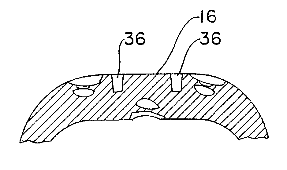
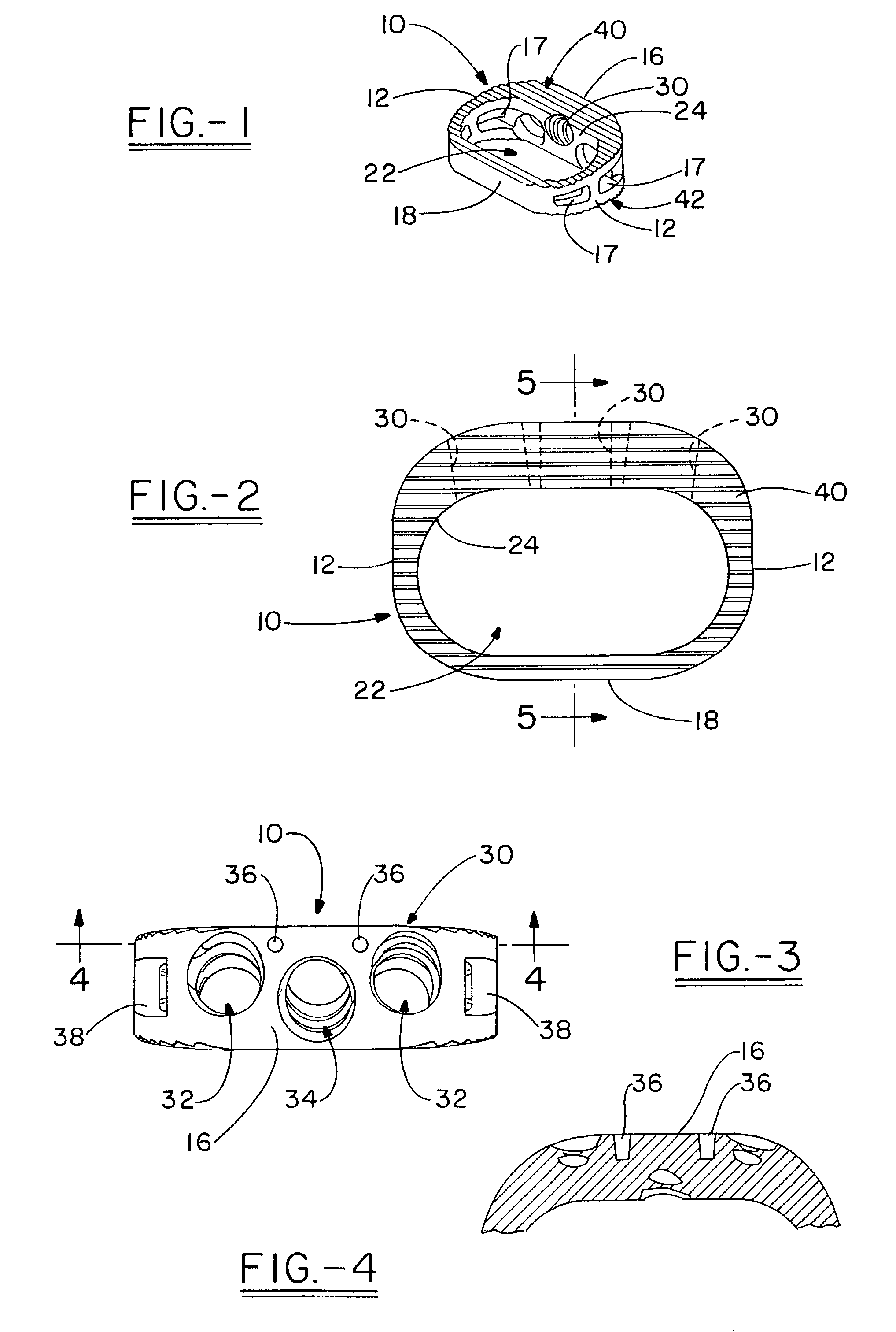
[0036]The present invention provides a vertebral space or cage, shown generally in FIG. 1. The cage 10 has a bracelet or oval peripheral shape with opposing front 16 and rear 18 walls that are generally solid, and are connected by curved side walls 12, that each include double openings, or fenestrations 17 that have a substantially rhomboid outline to maximize the area of visual access to the interior of the cage. The cage is hollow with a center opening 22 defined by a smooth continuous interior surface 24 that generally corresponds to the smooth continuous exterior surface of the cage 10. Further, the cage 10 includes a taper decreasing in height from front to back to provide a wedge shape which is lower at the back (i.e. posterior wall). Differing size cages may be provided with differing amounts of taper depending on the level of the spine where the cage is being implanted. Typically the cage is used to replace a disc, however, it is possible that the cage could be sized and use...


PUM


Abstract

A vertebral cage is provided for use in preserving the space between adjacent vertebral during the process of spinal fusion. In particular, this cage has an open modified oval peripheral shape with a continuous fluid anterior wall having angled screw passages accessible through co-planar openings to allow the construct to be stabilized between adjacent vertebral bodies through their endwalls. In addition, the cage has a back to front wedge taper with pull-out resistant ratchet surfaces. Further, in a second aspect of the invention, the screw passages have a unique locking mechanism provided by oversized internal threads in combination with a second locking thread on the head of the associated bone screws that allows for axial translation of the screws within the screw passages. This in turn permits play in the angulation of the screw relative to the anchoring bone in order to optimize the screw placement in the bone.

Description

[0001]This patent application is based upon U.S. Provisional Application Ser. No. 60 / 356,373, filed Feb. 12, 2002.[0002]The invention relates to a vertebral cage for use in preserving the space between adjacent vertebrae during the process of spinal fusion. In particular, this cage has a back to front wedge taper and an open modified oval peripheral shape with an anterior wall having angled screw passages to allow the construct to be stabilized between adjacent vertebral bodies through their end-walls. Further, in a second aspect of the invention, the screw passages have a unique locking mechanism in combination with the associated bone screws that allows for axial translation of the screws within the screw passages. This in turn permits play in the axial and radial position of the screws in the screw passages and in the angulation of the screw relative to the anchoring bone in order to optimize the screw placement in the bone and to minimize threading difficulties such as cross thr...

Claims


Application Information

Patent Timeline
Patent Type & Authority Patents(United States)
IPC IPC(8): A61F2/44A61F2/00A61F2/28A61F2/30A61F2/46
CPCA61F2/447A61F2310/00179A61F2002/2835A61F2002/30266A61F2002/30774A61F2002/30777A61F2002/30787A61F2002/30794A61F2002/30841A61F2002/30904A61F2002/4475A61F2230/0082A61F2310/00017A61F2310/00023A61F2310/00161A61F2/4611A61F2002/30593A61F2002/3079
Inventor BYRD, III, JOHN ABBOTTTIMM, JENS PETER
Owner ZIMMER BIOMET SPINE INC
Why Eureka
Try Eureka