Mounting mechanism for storage device

a storage device and mounting mechanism technology, applied in the direction of curtain suspension devices, electric apparatus casings/cabinets/drawers, instruments, etc., can solve the problems of boring screw manipulation, complicated and time-consuming screw manipulation, etc., and achieve the effect of facilitating the attachment of a storage devi

Inactive Publication Date: 2006-07-18
HON HAI PRECISION IND CO LTD
View PDF7 Cites 10 Cited by
  • Summary
  • Abstract
  • Description
  • Claims
  • Application Information

AI Technical Summary

Benefits of technology

[0007]Accordingly, an object of the present invention is to provide a mounting mechanism which facilitates the attachment of a storage device to a computer chassis.
[0008]Another object of the present invention is to provide a mounting mechanism which can simultaneously secure two internal devices to a computer chassis without use of screws.

Problems solved by technology

It is complicated and time-consuming to manipulate screws.
It is boring to manipulate screws to detach the hard disk drive from the box when in need.

Method used


Image

  • Mounting mechanism for storage device
  • Mounting mechanism for storage device
  • Mounting mechanism for storage device

Examples


Embodiment Construction

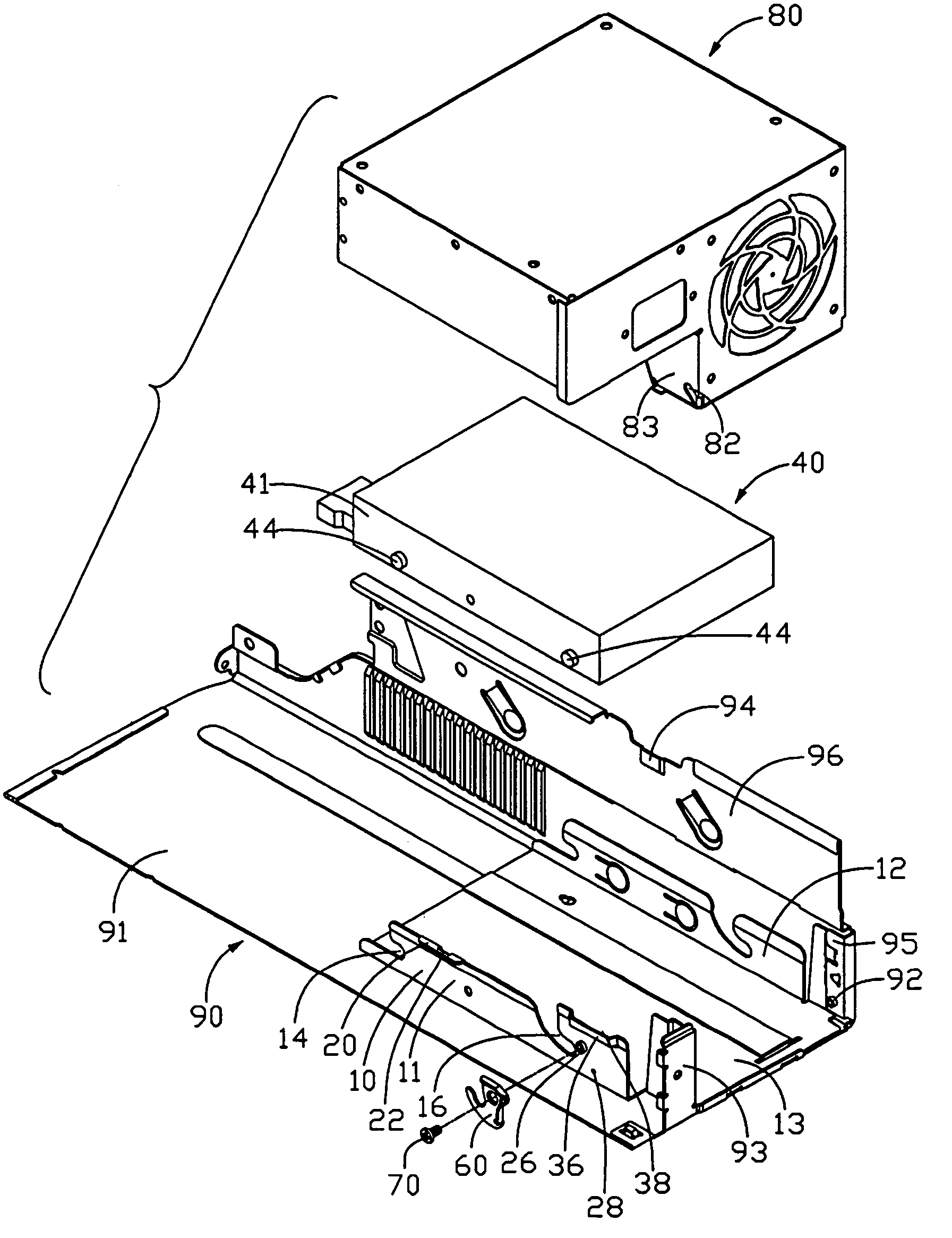
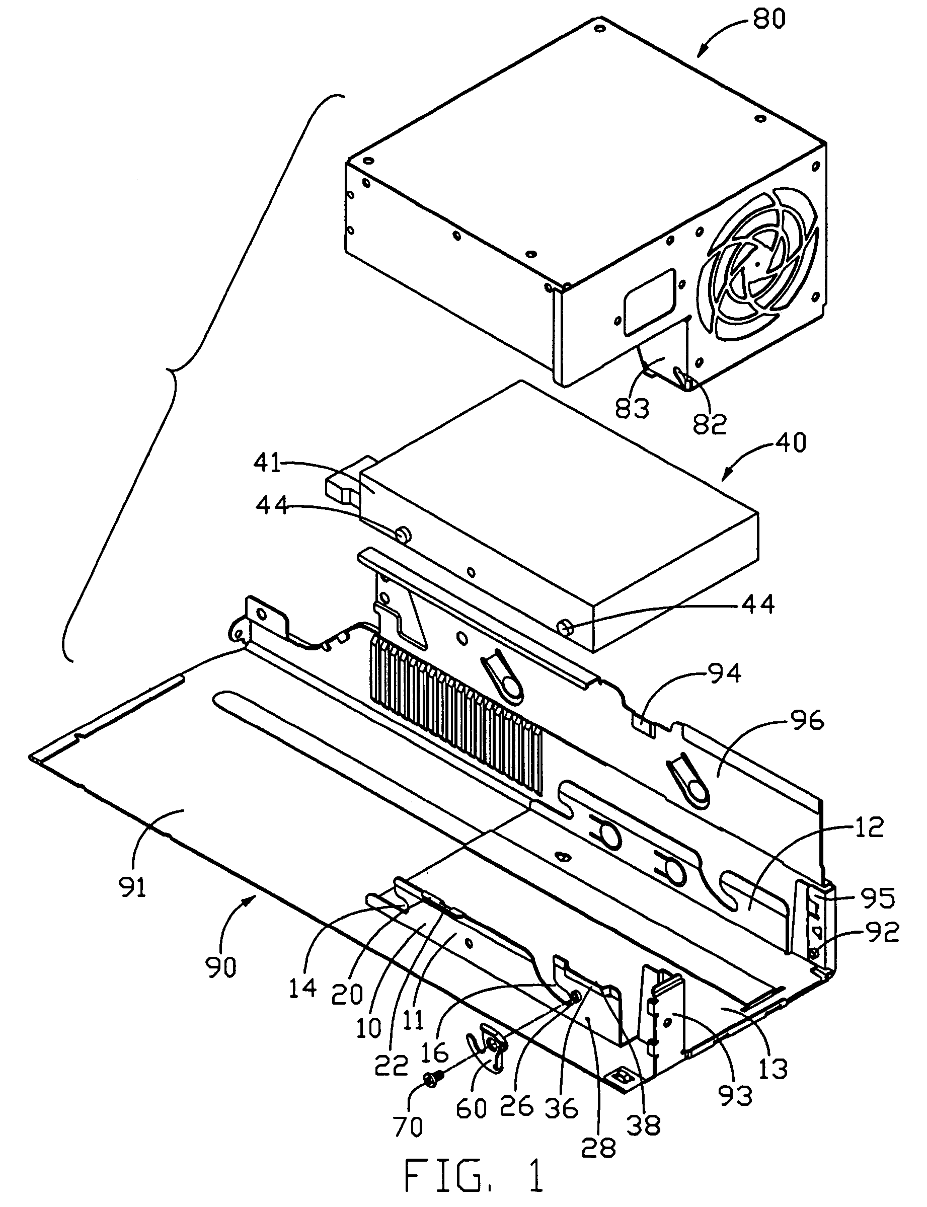
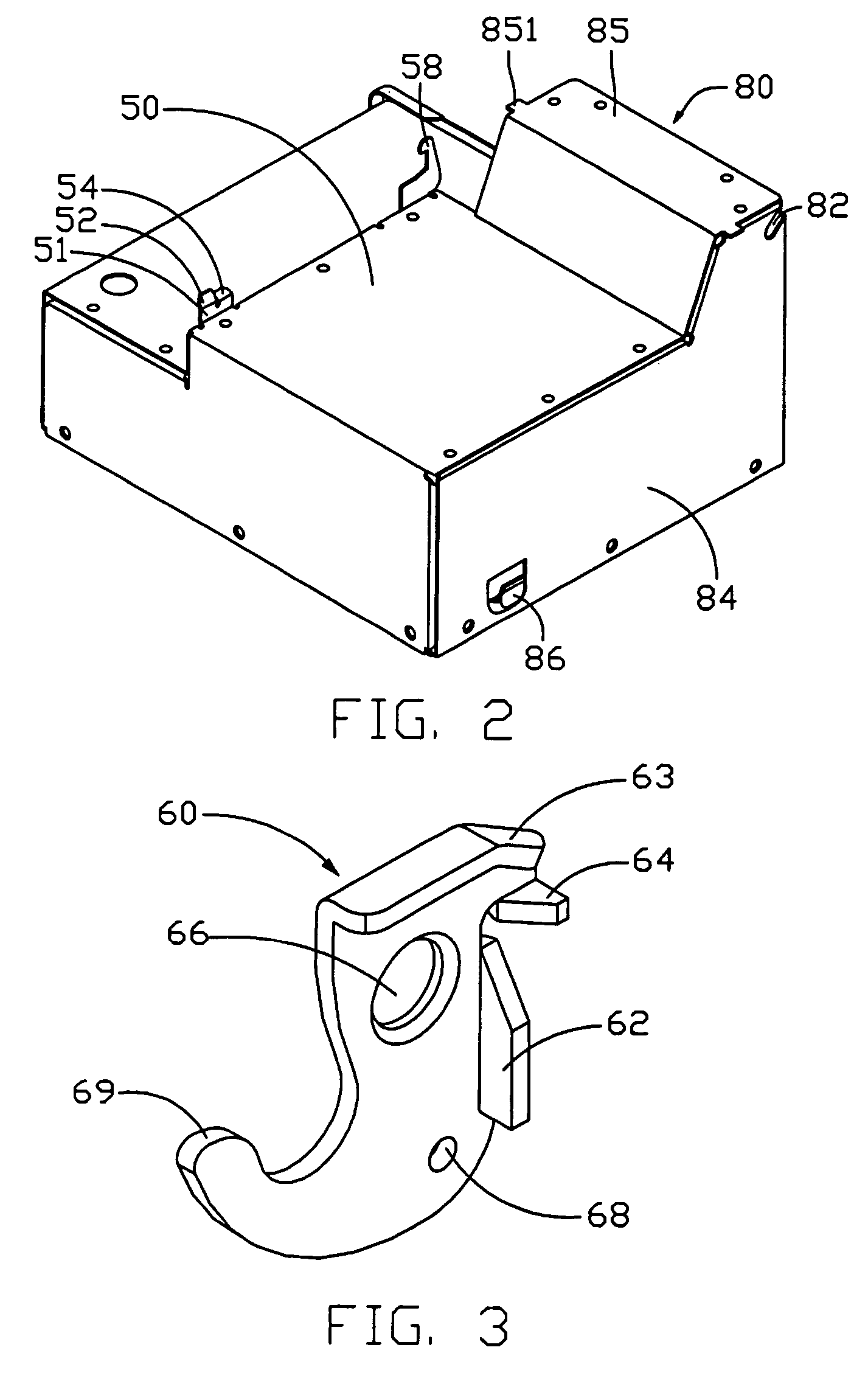
[0020]Referring to FIG. 1, a mounting mechanism in accordance with the preferred embodiment of the present invention is provided for holding a storage device 40 in place. The mounting mechanism comprises a bracket 10 attached to a computer chassis 90, a hook 60 as a securing member and an internal device such as a power supply 80.

[0021]The computer chassis 90 comprises a first wall 91 and a second wall 96 perpendicularly extended from a longitudinal edge of the first wall 91. A bent plate 93 is formed from a rear end of the first wall 91. A bent plate 95 is bent forwardly from a rear edge of the second wall 96. A pivot 92 is formed on a side face of the second wall 96 at a lower rear portion thereof. Another pivot (not visible) is formed on a side face of the bent plate 93, corresponding to the pivot 92 of the second wall 96. A groove 94 is stamped inwardly adjoining a cutout at upper portion of the second wall 96.

[0022]The bracket 10 comprises a pair of sidewalls 11, 12, and a bott...


PUM

PropertyMeasurementUnit
gravityaaaaaaaaaa
timeaaaaaaaaaa
poweraaaaaaaaaa

Abstract

A mounting mechanism includes a computer chassis (90), a bracket (10) defining a pair of slideways (14, 16) in a sidewall (11) thereof for receiving corresponding sliding members (44) of a storage device (40), a power supply (80) rotatably attached in the computer chassis, and a hook (60, 60′) pivotally attached to the sidewall of the bracket. The hook is for retaining the sliding members of the storage device in the slideways of the bracket. The power supply is rotated to engage the bracket and the hook thereby securing the storage device in the bracket.

Description

BACKGROUND OF THE INVENTION[0001]1. Field of the Invention[0002]The present invention relates to a mounting mechanism for storage device, and more particularly to a mounting mechanism which facilitates attachment of a storage device to a computer chassis.[0003]2. Description of the Related Art[0004]Computers have been widely used in modern life. It is desirable for a user or technician to conveniently access internal devices such as storage devices, expansion cards and Motherboard for purpose of service. However, storage devices, such as hard disk drives, compact disk read-only memory (CD-ROM) drives, digital video disc (DVD) drives, floppy disk drives, and the like are typically secured in computer chassis with screws or bolts. It is complicated and time-consuming to manipulate screws.[0005]As disclosed in U.S. Pat. No. 5,349,483, a hard disk drive is firstly attached to a sliding box with screws, and the sliding box is inserted in a chamber on a computer chassis and releasably loc...

Claims


Application Information

Patent Timeline
Patent Type & Authority Patents(United States)
IPC IPC(8): G06F1/16G06F1/18G11B33/12H05K7/12H05K7/20
CPCG06F1/184G11B33/124G06F1/188G06F1/187
Inventor CHEN, YUN-LUNGWANG, LING-LAI
Owner HON HAI PRECISION IND CO LTD
Why Eureka
Try Eureka