Pattern recognition

a pattern recognition and pattern technology, applied in image analysis, instruments, computing, etc., can solve the problems of inadequate feed-forward approach and slow processing speed, and achieve the effect of less arithmetic capability and effective implementation

Inactive Publication Date: 2006-07-18
SIEMENS AG
View PDF9 Cites 25 Cited by
  • Summary
  • Abstract
  • Description
  • Claims
  • Application Information

AI Technical Summary

Benefits of technology

[0022]The technical advantage of the technique represented is, in particular, that the detection can be performed serially in the learning and / or recognition phase. By contrast with a parallel overall detection of the information of a pattern to be learned or to be recognized, this serial detection requires less arithmetic capability and can be effectively implemented with the aid of classical serial computing architecture.

Problems solved by technology

It has emerged in the meantime that this feed-forward approach is inadequate in the case of technical implementation in that the resulting processing speeds are too slow.

Method used


Image

  • Pattern recognition
  • Pattern recognition
  • Pattern recognition

Examples


Embodiment Construction

[0026]Reference will now be made in detail to the preferred embodiments of the present invention, examples of which are illustrated in the accompanying drawings, wherein like reference numerals refer to like elements throughout.

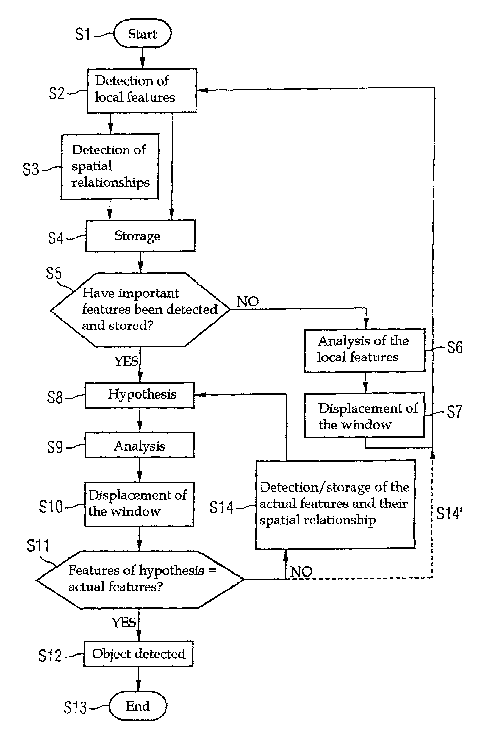
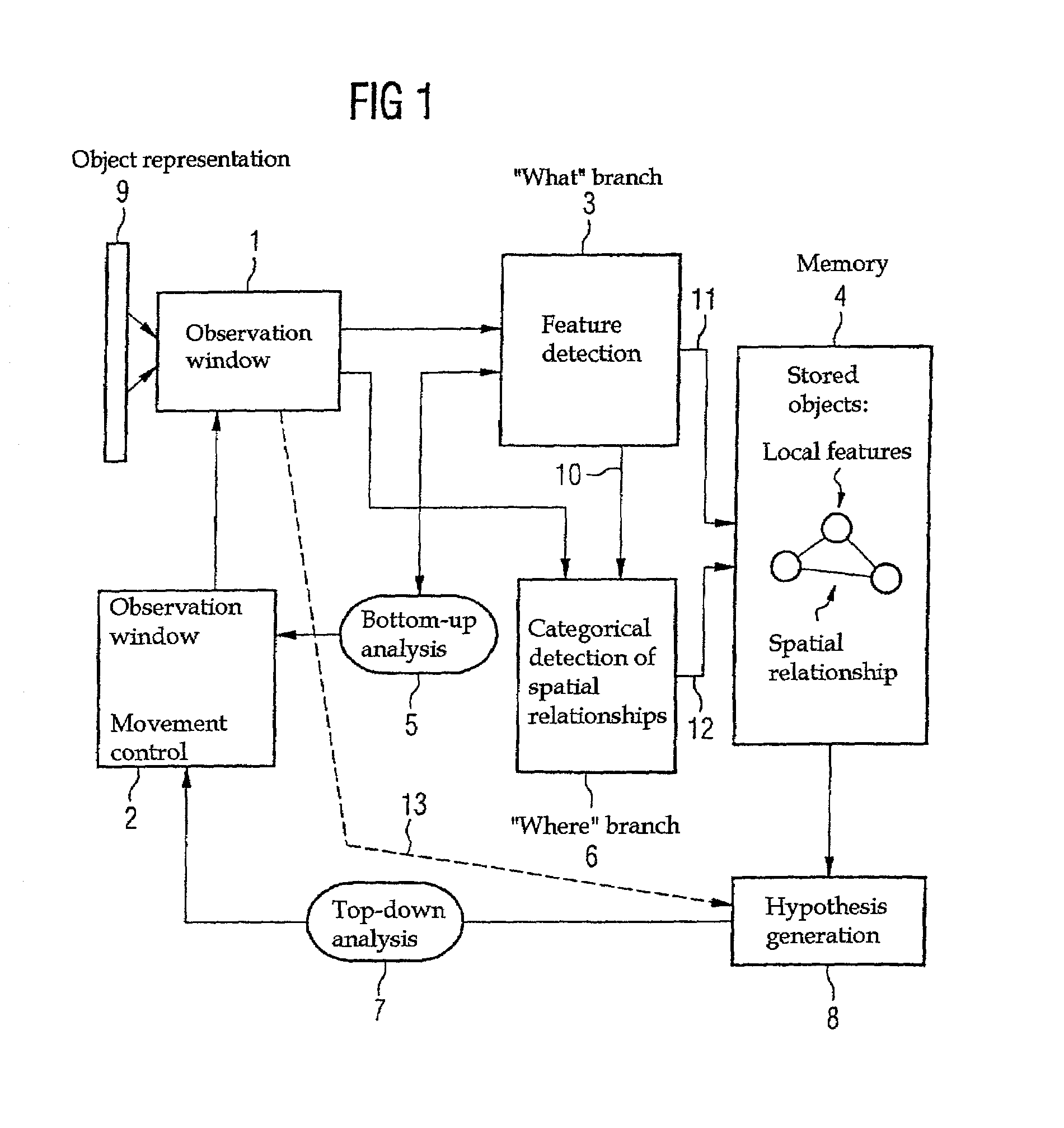
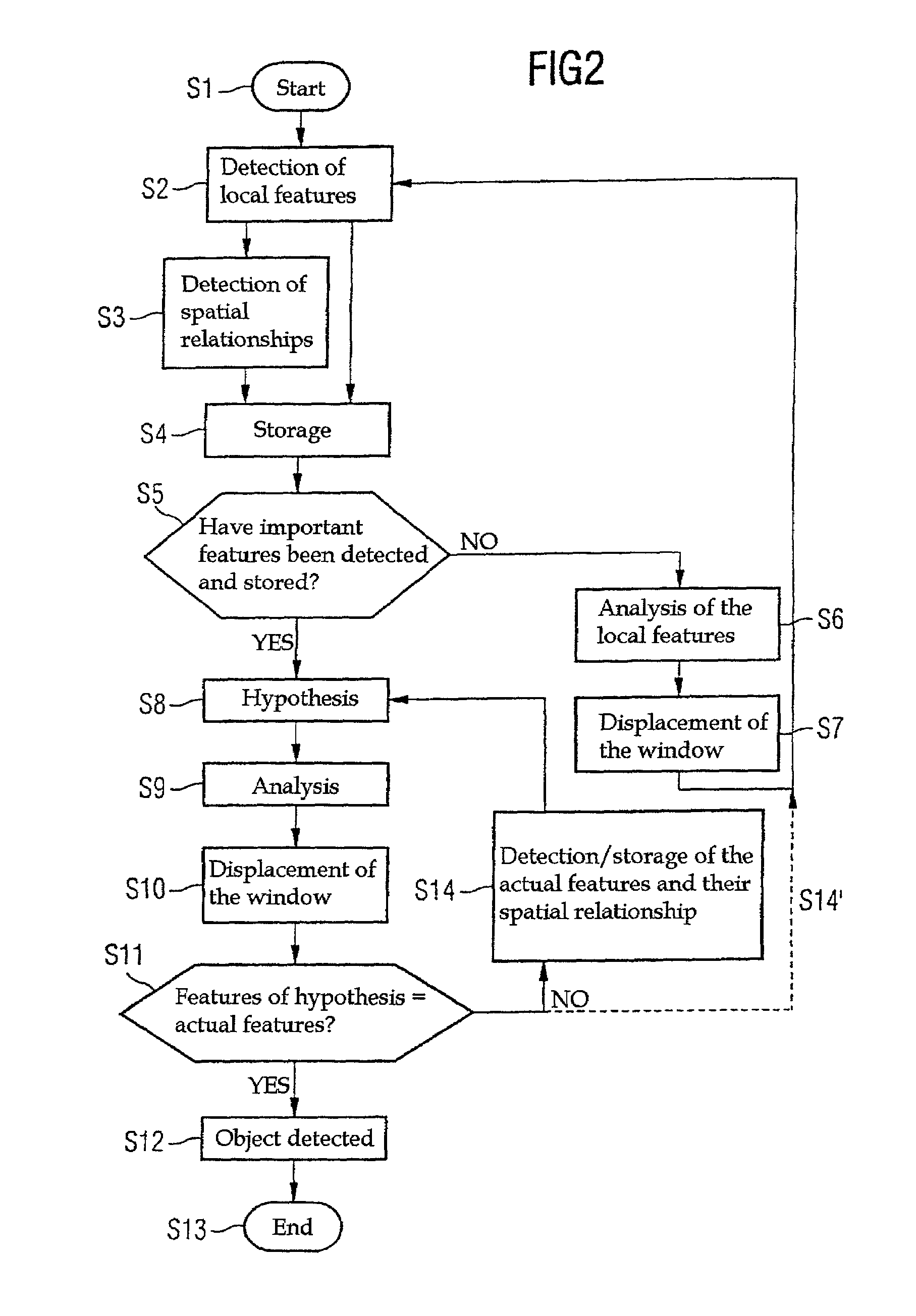
[0027]Referring to FIG. 1, the aim firstly is to explain the subassemblies of a system according to the invention for recognizing patterns. A flowchart which explains the controlled interaction of these subassemblies is therefore explained with reference to FIG. 2.

[0028]It may be mentioned that, in accordance with the exemplary embodiments, the recognition is performed visually, but that the invention can likewise be designed on the basis of other sensory perceptions such as, for example, acoustic perceptions.

[0029]In this case, the reference numeral denotes in FIG. 1 means for completely representing a pattern (object) to be recognized. These means can be, for example, a planar image sensor 9. The reference numeral 1 denotes in FIG. 1 means which can displac...


PUM


Abstract

In a pattern recognition system, a pattern which is to be recognized later is prescribed in a learning phase. This pattern is detected sequentially, that is to say the informative areas of the pattern are detected and, moreover, the spatial relationship between the areas is also stored. In the recognition phase, a hypothesis which indicates a presumed pattern and, furthermore, indicates where such further prominent areas should be located in the pattern to be recognized if the presumption is correct, is generated on the basis of the acquired data of a first area of a pattern to be recognized, and on the basis of the stored data. Thus, patterns are learned through their location information, on the one hand, and through their spatial relationship to each other, on the other hand, stored and then re-recognized. The application options of the present invention reside, for example, in robotics, text analysis and image analysis, but also in the field of medical technology (for example in automatic tumor detection in mammographies, etc).

Description

CROSS REFERENCE TO RELATED APPLICATIONS[0001]This application is based on and hereby claims priority to Patent Application No. 19924010.8 filed on May 26, 1999 in Germany, the contents of which are hereby incorporated by reference.BACKGROUND OF THE INVENTION[0002]1. Field of the Invention[0003]The present invention relates in general to the field of pattern recognition and, more particularly, to a learning method for a pattern recognition system, to a method for re-recognizing at least one pattern, to a pattern recognition system and to the use of such a pattern recognition system.[0004]2. Description of the Related Art[0005]Pattern recognition herein refers to predetermined patterns to be re-recognized which are fed in advance to a technical system or, in other words, that the pattern recognition system is trained. The pattern recognition system is intended to re-recognize later these patterns on which it has been trained in advance.[0006]In this case, “pattern” in the meaning of t...

Claims


Application Information

Patent Timeline
Patent Type & Authority Patents(United States)
IPC IPC(8): G06K9/46G06T7/00G06V10/20
CPCG06T7/00G06K9/80G06V10/20
Inventor DECO, GUSTAVOSCHUERMANN, BERND
Owner SIEMENS AG
Why Eureka
Try Eureka