
Hand tool with multiple locking blades controlled by a single locking mechanism and release

a technology of locking blades and locking mechanisms, which is applied in the direction of multi-purpose tools, wrenches, manufacturing tools, etc., can solve the problems of inconvenient use, insufficient use, and limited strength and robustness of their structure, and achieve the effect of the same results and performan

Inactive Publication Date: 2006-07-25
LEATHERMAN TOOL GROUP
View PDF92 Cites 14 Cited by
  • Summary
  • Abstract
  • Description
  • Claims
  • Application Information

AI Technical Summary

Benefits of technology

[0011]There is, additionally, means for biasing one of the blades toward the open position while biasing all others of the blades toward the closed position. This biasing means preferably takes the form of a first cam surface on the peripheral surface of each blade base at a location adjacent to the notch, having a first cam maximum surface height and a first cam maximum surface height angular position, and a second cam surface on the peripheral surface of the blade base at a location remote from the notch, having a second cam surface height less than the first cam surface height and a second cam maximum surface height angular position located about 110 to about 120 degrees from the first cam maximum surface height angular position. The first cam maximum surface height is preferably slightly smaller than the second cam maximum surface height.
[0012]Thus, the invention provides a locking / biasing mechanism that positively locks any one of the blades into its open position while biasing the remaining blades toward their closed positions. The locking mechanism has a single release that releases the blade that is locked into the open position. As the selected blade is opened or closed against its biasing force, the other blades remain in their closed positions under the influence of their biasing forces. Subsequently, a different blade may be selected for opening, with the same results and performance.

Problems solved by technology

Generally, Swiss Army knives are designed to be sufficiently small and light for carrying in a pocket and are therefore limited as to the strength and robustness of their structure.
Positive locks used in conjunction with biasing structures are desirable features of knives, but they have not been successfully utilized in knives having multiple blades rotating in the same direction on a common axle.
Such a “blade” therefore includes, but is not limited to, a sharpened knife blade, a serrated blade, a screwdriver, an awl, a bottle opener, a can opener, a saw, a file, etc.) Existing approaches have internal structures that require too much space when adapted for use on several side-by-side blades, or the locking release controls take up too much space or are inconvenient.
If the width of the handle of the hand tool is increased significantly above about 1 inch, the combination tool will no longer be comfortable in the hand.
There have been some attempts to provide a positive lock for the blades of a combination tool, but they have been highly inconvenient to use in practice.

Method used


Image

  • Hand tool with multiple locking blades controlled by a single locking mechanism and release
  • Hand tool with multiple locking blades controlled by a single locking mechanism and release
  • Hand tool with multiple locking blades controlled by a single locking mechanism and release

Examples


Embodiment Construction

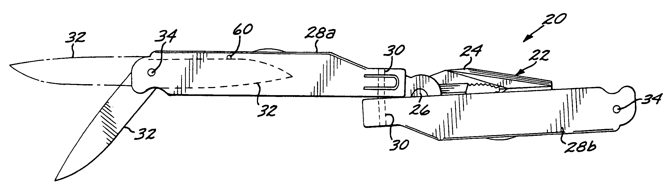
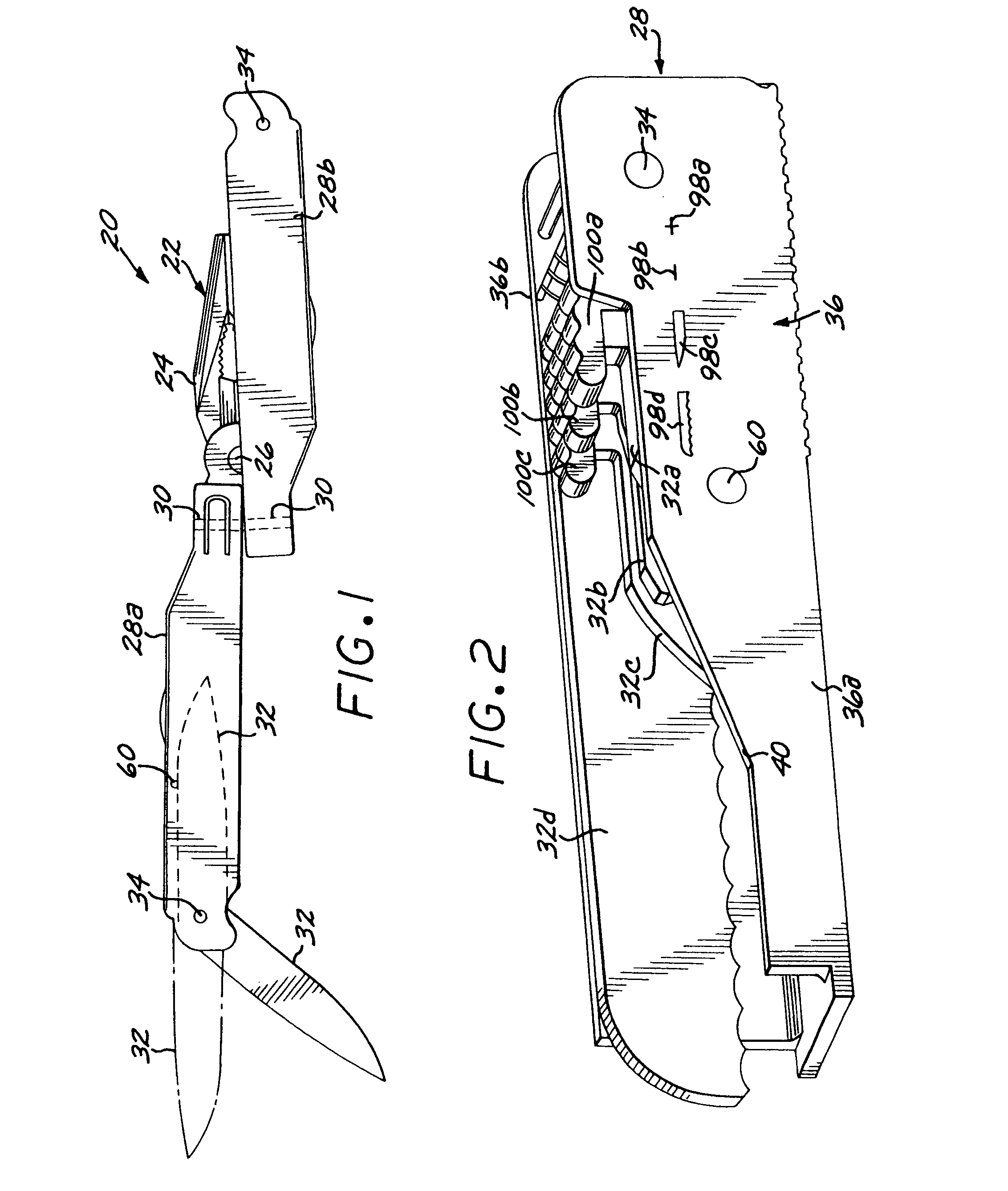
[0030]FIG. 1 illustrates a hand tool in the form of a combination tool 20 including a jaw mechanism 22 with two jaws 24 pivotably connected by a jaw pivot 26. Two handles 28 are deployably connected to the jaws 24 by handle pivot pins 30. The handles 28 are channel sections. In the view of FIG. 1, one of the handles 28a is in a deployed position and the other of the handles 28b is in a nested position. A number of different combination tools of various configurations are known, see, for example, U.S. Pat. Nos. 4,238,862; 4,744,272; 5,142,721; 5,212,844; 5,267,366; and 5,062,173, whose disclosures are incorporated by reference, and several types are available commercially.

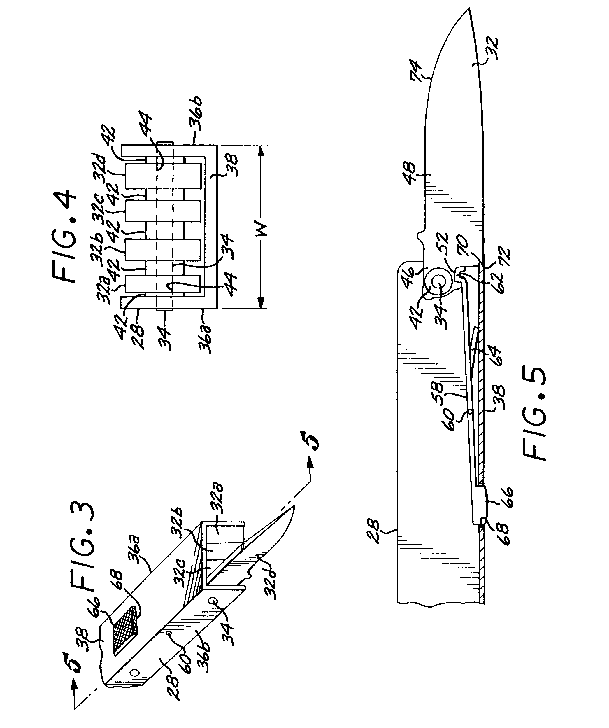
[0031]In the combination tool 20, those described in the referenced patents, and those available commercially, it is common practice to affix a plurality of blade tools 32 in each of the handles 28 to increase the utility of the combination tool. The blade tools 32 are pivotably connected by a tool pivot axle 34 to ...


PUM


Abstract

A hand tool such as a knife or a combination tool includes multiple blades, each independently rotatable on a common axle between a closed position within a handle of the tool and an open position extending from the handle. Each blade is positively but releasably locked into its open position. Those blades which remain closed are biased toward the closed position when the opened blade is locked into position and also as it is opened and closed. A single locking, releasing, and biasing mechanism serves all of the blades in one handle.

Description

CROSS-REFERENCE TO RELATED APPLICATIONS[0001]This application is a continuation of application Ser. No. 10 / 309,735, filed Dec. 3, 2002, now U.S. Pat. No. 6,802,094, for which priority is claimed and whose disclosure is incorporated by reference in its entirety; which is a continuation of application Ser. No. 09 / 847,559, filed May 1, 2001, now U.S. Pat. No. 6,487,740, for which priority is claimed and whose disclosure is incorporated by reference in its entirety; which is in turn a continuation of application Ser. No. 09 / 660,256, filed Sep. 12, 2000, now U.S. Pat. No. 6,233,769, for which priority is claimed and whose disclosure is incorporated by reference in its entirety; which in turn is a continuation of application Ser. No. 09 / 060,768, filed Apr. 14, 1998, now U.S. Pat. No. 6,170,104, for which priority is claimed and whose disclosure is incorporated by reference in its entirety; which in turn is a continuation of application Ser. No. 08 / 606,169, filed Jan. 11, 1996, now U.S. Pa...

Claims


Application Information

Patent Timeline
Patent Type & Authority Patents(United States)
IPC IPC(8): B25B7/22B25F1/00B26B1/02B26B1/04B26B11/00
CPCB25F1/003B26B1/048B26B1/042
Inventor SEBER, BRETT P.MORTON, RANDOLPH J.DRAGUICEVICH, GABRIEL ALEJANDROHELTON, JR., ROY L.RUBIN, GREGORY F.
Owner LEATHERMAN TOOL GROUP
Learn More