Phased shifted oscilator and antenna

Active Publication Date: 2010-04-29
BEAM NETWORKS
View PDF3 Cites 10 Cited by
  • Summary
  • Abstract
  • Description
  • Claims
  • Application Information

AI Technical Summary

Benefits of technology

[0018]In exemplary embodiments of the invention, the narrow beams allow a wider coverage range or a lower electromagnetic interference than conventional antenna based on prior art

Problems solved by technology

Conventional PAA are extremely expensive and of high power-consumption, therefore they are mainly used in military applications, such as aircraft radars and missile-radars.
For instanc

Method used


Image

  • Phased shifted oscilator and antenna
  • Phased shifted oscilator and antenna
  • Phased shifted oscilator and antenna

Examples


Embodiment Construction

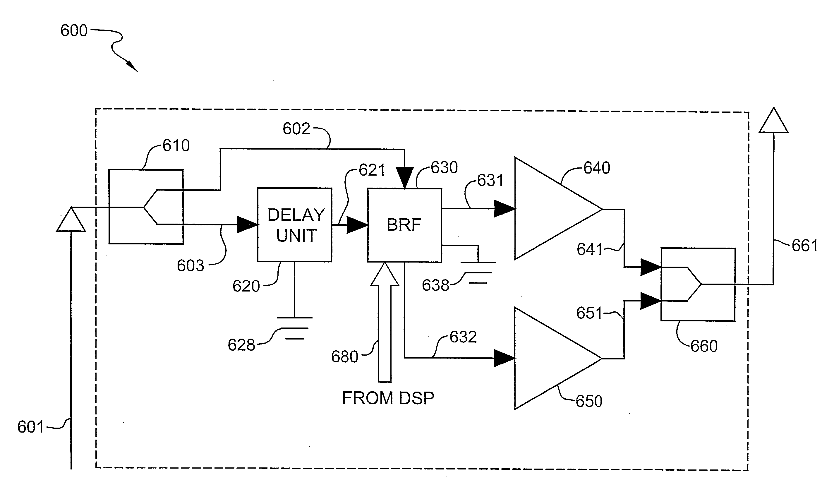
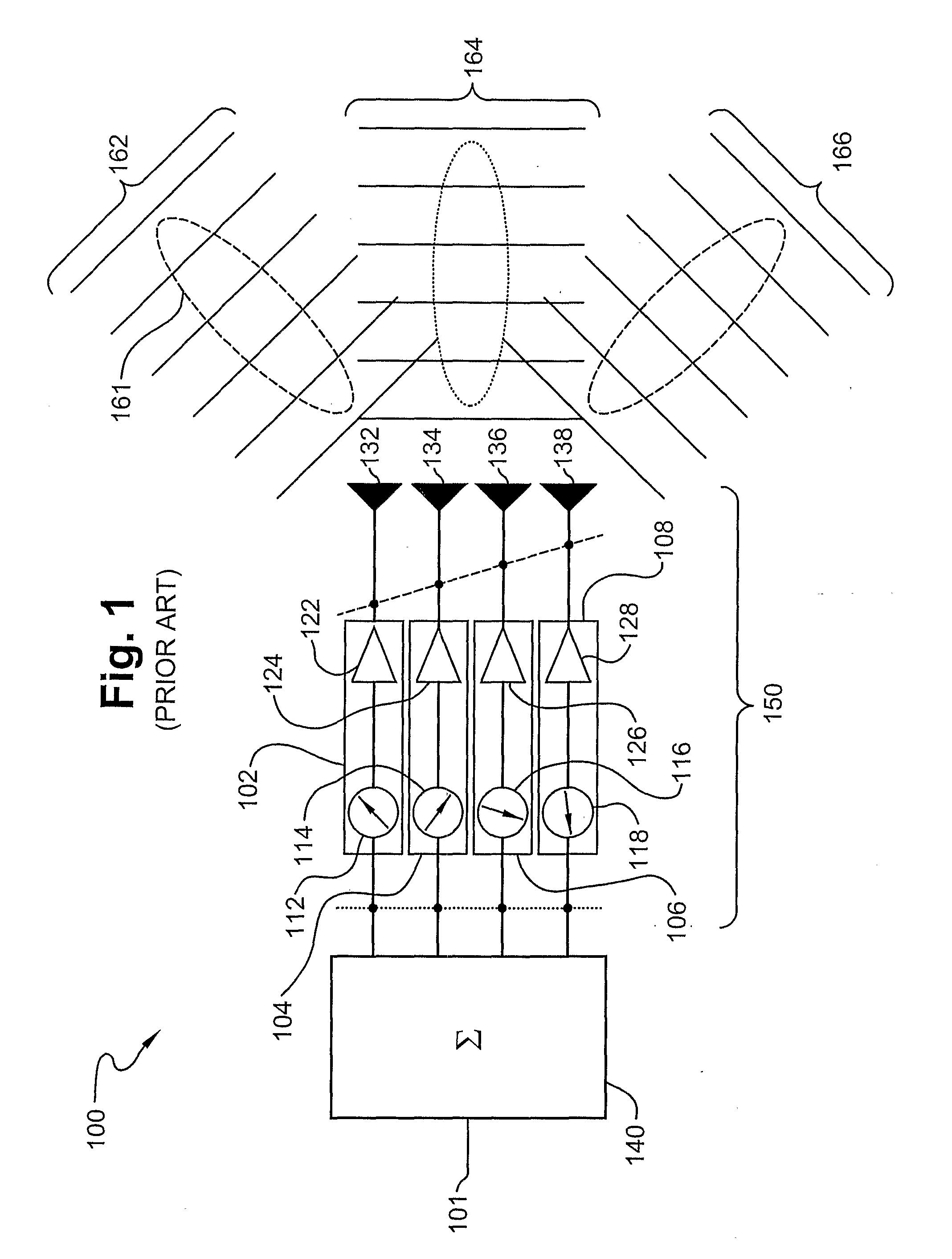
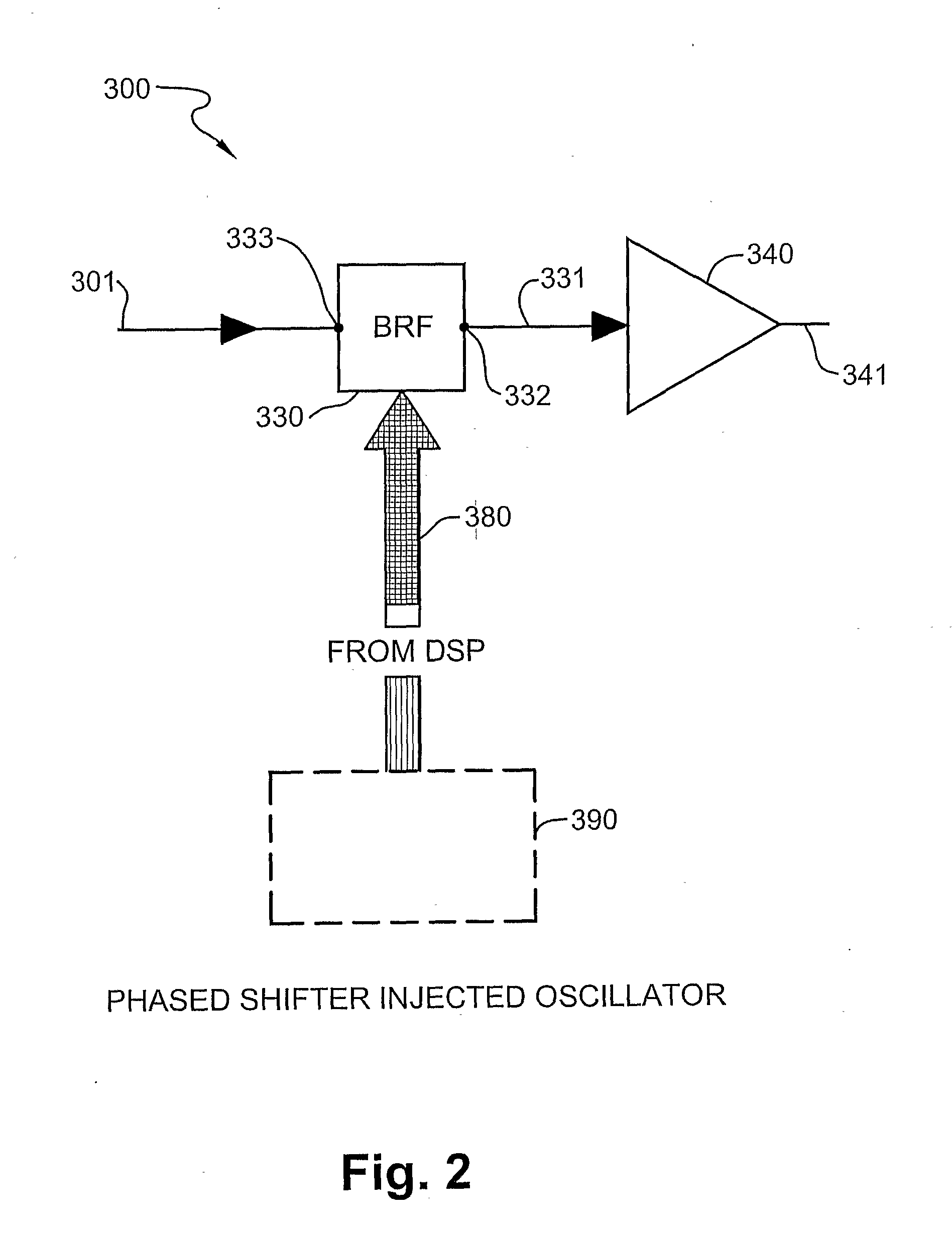
[0037]This invention describes new and improved phased shifted injection oscillator, a phased shifted injection locked push-push oscillator and a phased array antennas (PAA). The PAAs in accordance with an exemplary embodiment of the present invention are low cost, and therefore can be used in various commercial applications, such as wireless communication or satellite mobile television. The PAAs of the present invention provides significant enhancements and improvements over prior art PAA, as will be shown from the specifications and figures.

[0038]A phased array antenna according to the present invention comprises a plurality phase shifting elements and other electronic components. Conventional phase shifters are expensive electronic components or are affected by high RF loss. Both, cost and RF loss contribute to the very high cost of conventional phased array antenna using conventional T / R modules or conventional phase shifters.

[0039]In an exemplary embodiment of the invention a p...


PUM


Abstract

This invention describes new and improved phased shifted injection oscillator, a phased shifted injection locked push-push oscillator and a phased array antennas (PAA). The PAAs in accordance with an exemplary embodiment of the present invention are low cost, and therefore can be used in various commercial applications, such as wireless communication or satellite mobile television.

Description

FIELD OF THE INVENTION[0001]The present invention relates generally to a device and process for sending and receiving radio wave energy for utilizing information, and more specifically to phased array antennas and their application in wireless communication.BACKGROUND OF THE INVENTION[0002]Antennas are designed to transmit and receive electro-magnetic waves. A phased array antenna is an antenna comprising 4 plurality of radiator elements (radiators) with a directive radiation pattern (beam) which can be controlled by controlling individual radiator elements (radiators) or groups of radiator elements in the antenna. In general, the steering direction of the radiation pattern is determined by control of the phases of the signal to or from the radiator elements. In conventional phased array antennas the phase control is achieved by phase shifters. The specific phases are typically determined by a digital signal processing (DSP) subsystem.[0003]One example of phased array antennas is di...

Claims


Application Information

Patent Timeline
IPC IPC(8): H01Q3/00H03F3/04
CPCH03B5/1852H01Q3/34H01Q3/38H01Q3/42H03L7/00
Inventor MILANO, ALBERTO
Owner BEAM NETWORKS
Why Eureka
Try Eureka