
Optimal Denoising for Video Coding

a video coding and denoising technology, applied in the field of digital signal processing, can solve the problems of many observers (both trained and untrained), time-consuming subjective quality evaluation, and loss of information in the coding process, and achieve the effect of the same or better performan

Active Publication Date: 2007-12-20
THE HONG KONG UNIV OF SCI & TECH
View PDF42 Cites 8 Cited by
  • Summary
  • Abstract
  • Description
  • Claims
  • Application Information

AI Technical Summary

Benefits of technology

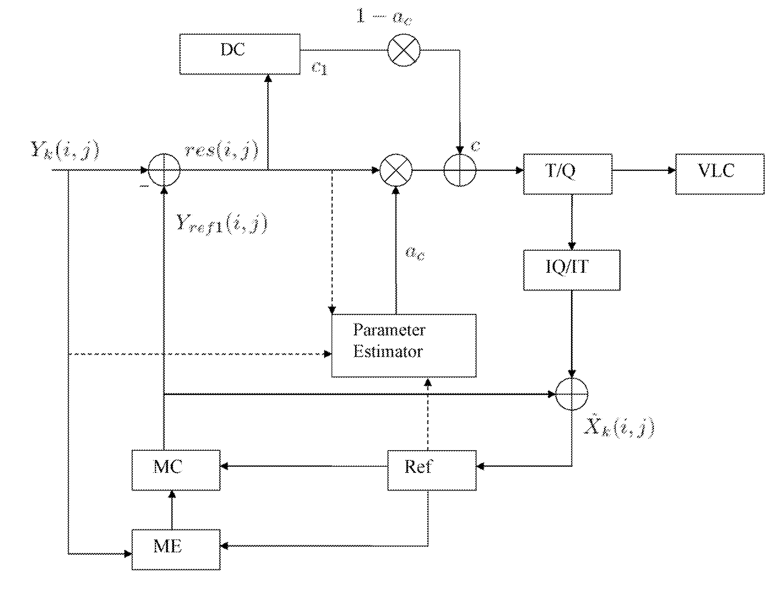
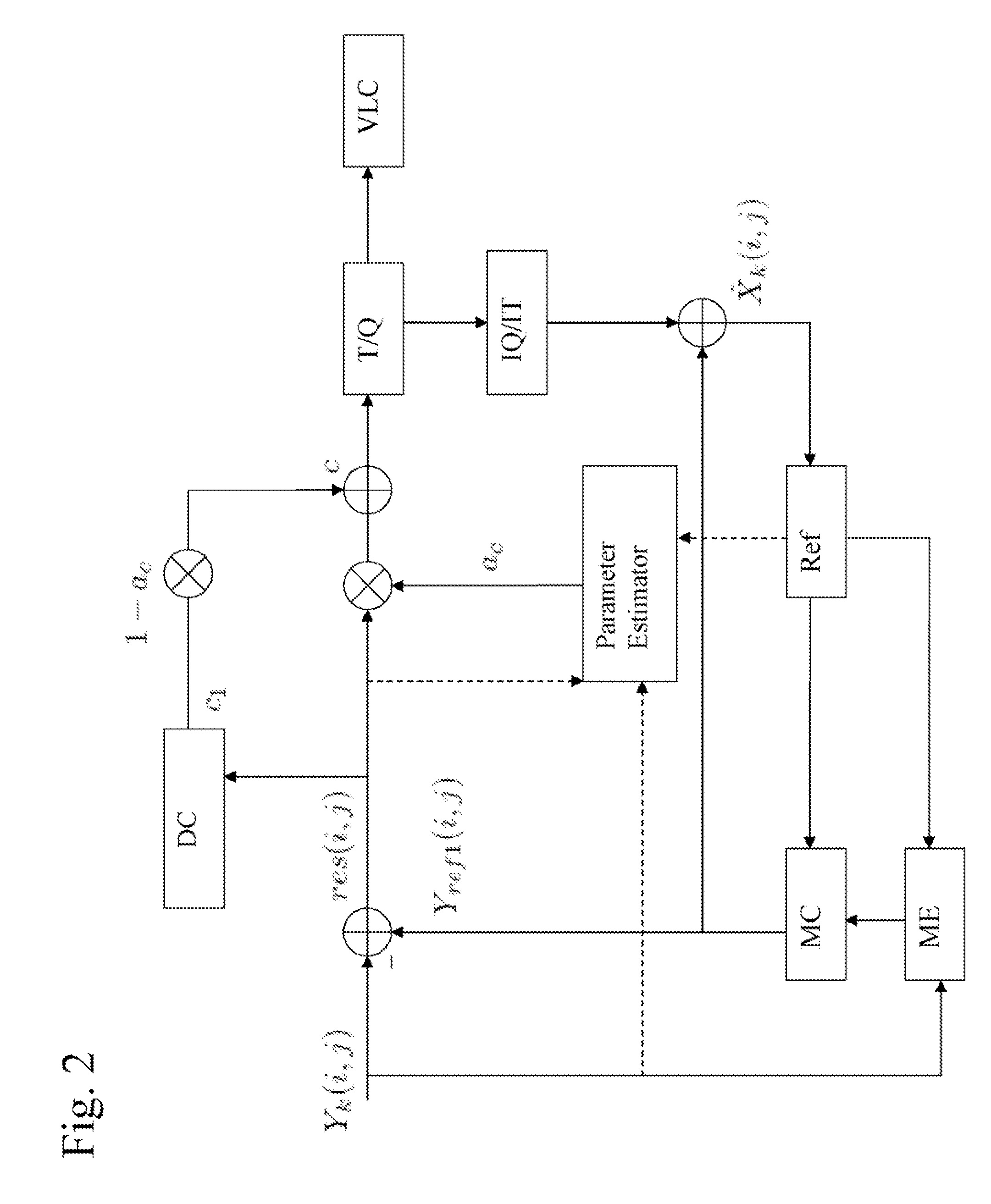
[0008] The present application proposes a new purely pre-processing denoising method named Multi-Hypothesis Motion Compensated Filter (MHMCF). This pre-processing denoising method is based on the temporal linear minimum mean square error (LMMSE) estimator and requires much fewer pixels (in our simulation 3 pixels are enough) as input than most existing denoising filters to achieve same or better performance. Based on the MHMCF, the application further proposes an improved denoising method named Embedded Optimal Denoising Filter (EODF). Unlike the purely pre-processing approach, this filter can be seamlessly embedded into the motion compensation process of video encoders with nearly no extra computation introduced.
[0011] This approach achieves better performance because the filter coefficients are determined based on linear minimum mean squared error estimator;
[0012] This approach is flexible because there is no limitation on the number of references involved in the filtering, and the more the references are, the better the performance is. Further, it allows the use of both past frames and future frames, of both previously denoised frames and the undenoised frames;
[0014] For P frames, video encoder with this approach embedded is compatible with MPEG-1, MPEG-2, MPEG-4, H.261, H.263, H.264 or AVS standards The standard can be modified easily to accommodate B frames; and
[0015] The approach produces encoded frame more visually pleasing. That is because the traditional methods preserve large amplitude High Frequency (HF) coefficients caused by noise. After inverse quantization and inverse transform, these HF coefficients would cause “mosaic” phenomena, which are very visually annoying.

Problems solved by technology

Due to internal quantization step, the hybrid coding scheme is a lossy coding process, which means that some information is lost in the coding process.
Therefore, the decoded (reconstructed) video has some distortion compared to the original (uncoded) video.
But subjective quality evaluation is time consuming and requires many observers (both trained and untrained).
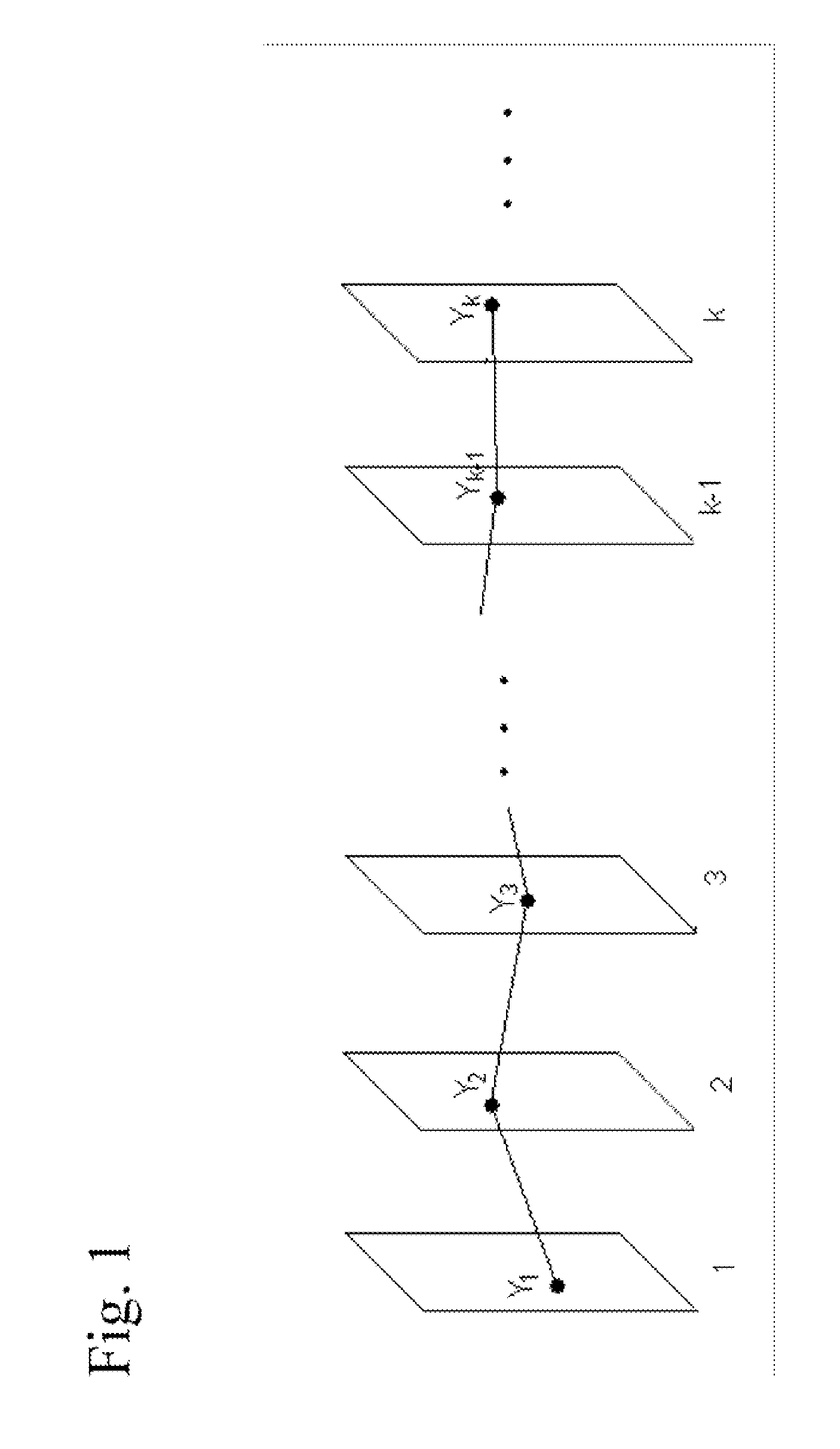
Unfortunately, digital video sequences are almost always corrupted by noise due to video acquisition, recording, processing and transmission.
A main source of the noise is the noise introduced by capture device (e.g. CCD or CMOS sensor), especially when the scene is dark leading to low signal-to-noise ratio.
Such noise introduced in video sequence is undesirable.
It degrades the subjective quality of the video.
It also affects the accuracy of motion estimation.
However, the noise is inherently independent among frames.
Thus the presence of noise reduces temporal redundancy among consecutive frames and this can decrease the accuracy of the motion vectors obtained in motion estimation.
Moreover, even if the motion vectors are accurate, the noise will make the residue frame noisy.
As the noise typically exhibits little spatial redundancy, the energy of the noisy residue frame cannot be compacted by DCT.
As a result coding performance could drop very significantly due to the presence of noise, with a large part of the bandwidth or bit rate wasted to represent the undesirable noise.
After inverse quantization and inverse transform, these HF coefficients would cause “mosaic” phenomena, which are very visually annoying.

Method used


Image

  • Optimal Denoising for Video Coding
  • Optimal Denoising for Video Coding
  • Optimal Denoising for Video Coding

Examples


Embodiment Construction

[0021] The numerous innovative teachings of the present application will be described with particular reference to the presently preferred embodiment (by way of example, and not of limitation).

The Multi-Hypothesis Motion Compensated Filter (MHMCF)

[0022] As shown in FIG. 1, a video sequence is composed of many consecutive frames. In the video sequence, assume there is a point object which can be tracked in all the frames. Suppose the original intensity value of this point object in frame k is Xk, and the observed value is

Yk=Xk+Nk.  (1)

where Nk is the undesirable noise. Nk is assumed zero mean, with variance σn2. It is also assumed that Nk is independent over space and time and independent of Xk.

[0023] Ideally, Xk should be the same for all k. However, due to many reasons including inaccurate motion estimation, changing light conditions, and deforming objects, Xk changes from one frame to another. This can be described as

Xk=Xi+Zi,k  (2)

where Zi,k represents the innovation in...


PUM


Abstract

An optimal denoising method for video coding. This method makes use of very few pixels and linear operations, and can be embedded into the motion compensation process of video encoders. This method is simple and flexible, yet offers high performance and produces appealing pictures.

Description

CROSS-REFERENCE TO OTHER APPLICATION [0001] The present application claims priority from U.S. provisional application No. 60 / 801,375 filed May 19, 2006, which is hereby incorporated by reference.BACKGROUND AND SUMMARY OF THE INVENTIONS [0002] The present application relates generally to digital signal processing, and more particularly to a video compression, coding, filtering and representation system utilizing temporal redundancy and having both device and method aspects. It further relates to a computer program product, such as a recording medium, carrying program instructions readable by a computing device to cause the computing device to carry out methods according to the inventions. Background: Noising in Video Coding [0003] The importance of video technology is constantly growing with the ever increasing use of television and video systems in consumer, commercial, medical and scientific applications. [0004] Due to the huge size of the raw digital video data (or image sequence...

Claims


Application Information

Patent Timeline
Patent Type & Authority Applications(United States)
IPC IPC(8): H04B1/66
CPCH04N19/86H04N19/61
Inventor AU, OSCAR CHI LIMGUO, LIWEI
Owner THE HONG KONG UNIV OF SCI & TECH
Learn More