Indentification device

a technology of indentification device and visible wavelength, which is applied in the direction of identification means, instruments, seals, etc., can solve the problems of limited application to ground-to-ground identification, inability to find suitable space on many vehicles, and inability to detect the background of thermal infrared wavelengths, etc., to achieve the effect of reducing thickness, reducing thickness, and being convenient to us

Inactive Publication Date: 2009-10-08
QINETIQ LTD
View PDF6 Cites 16 Cited by
  • Summary
  • Abstract
  • Description
  • Claims
  • Application Information

AI Technical Summary

Benefits of technology

[0043]Thus, a thermally reflective surface angled such that, when viewed from the same altitude, it reflects the sky directly overhead will appear unnaturally cold. It is this effect that is used in the present invention. Preferably, the reflective surface is a specular surface.
[0044]The identification system of the invention uses the principle of ‘cold sky reflection’ in a similar way to prior art identification devices, but, instead of utilising one or more inclined surfaces coated with a low emissivity, high reflectivity tape or paint, the system comprises a sheet of material having a surface texture comprising a plurality of inclined thermally reflective facets, preferably a micro-structured surface texture. This confers a number of important advantages. Because the reflection of thermal radiation through the desired angle is achieved using a thin layer of material, the identification system itself is thin, lightweight and easy to use, handle and install. Despite its reduced thickness, the identification system of the invention has the same or better performance than prior art systems and, moreover, tends to be robust and less susceptible to physical damage. Another benefit of the invention is the ease with which the sheet of thermally reflective material can be cut to size or otherwise tailored for use in an identification device.

Problems solved by technology

Accordingly, identification markings designed for use at visible wavelengths and near infrared wavelengths have little or no contrast with the background at thermal infrared wavelengths and are not generally discernible when viewed through thermal imagers.
Accordingly, the device of WO 2006 / 016094 is suitable for most air-to-ground identification scenarios, but has limited application to ground-to-ground identification by thermal infrared imaging.
Both types of system have a number of operational disadvantages; the first mode of use relies on the object to be marked having inclined surfaces in a suitable position (indeed, there may be no suitable location) whereas systems of the latter type tend to be bulky, cumbersome, susceptible to physical damage and their size can make it difficult to find suitable space on many vehicles.
Moreover, prior art systems tend to be particularly unsuitable for use on personnel and portable equipment.

Method used


Image

  • Indentification device
  • Indentification device
  • Indentification device

Examples


example 1

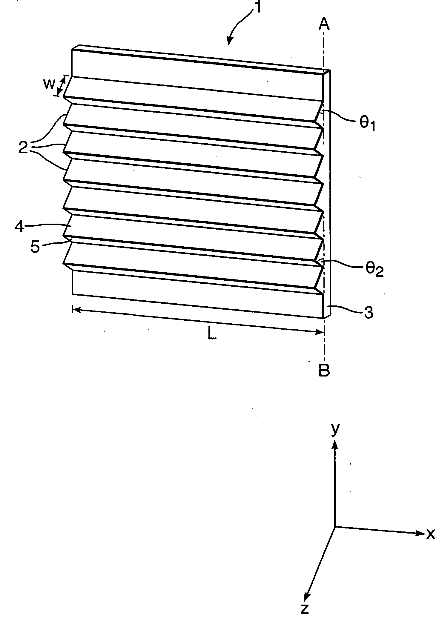
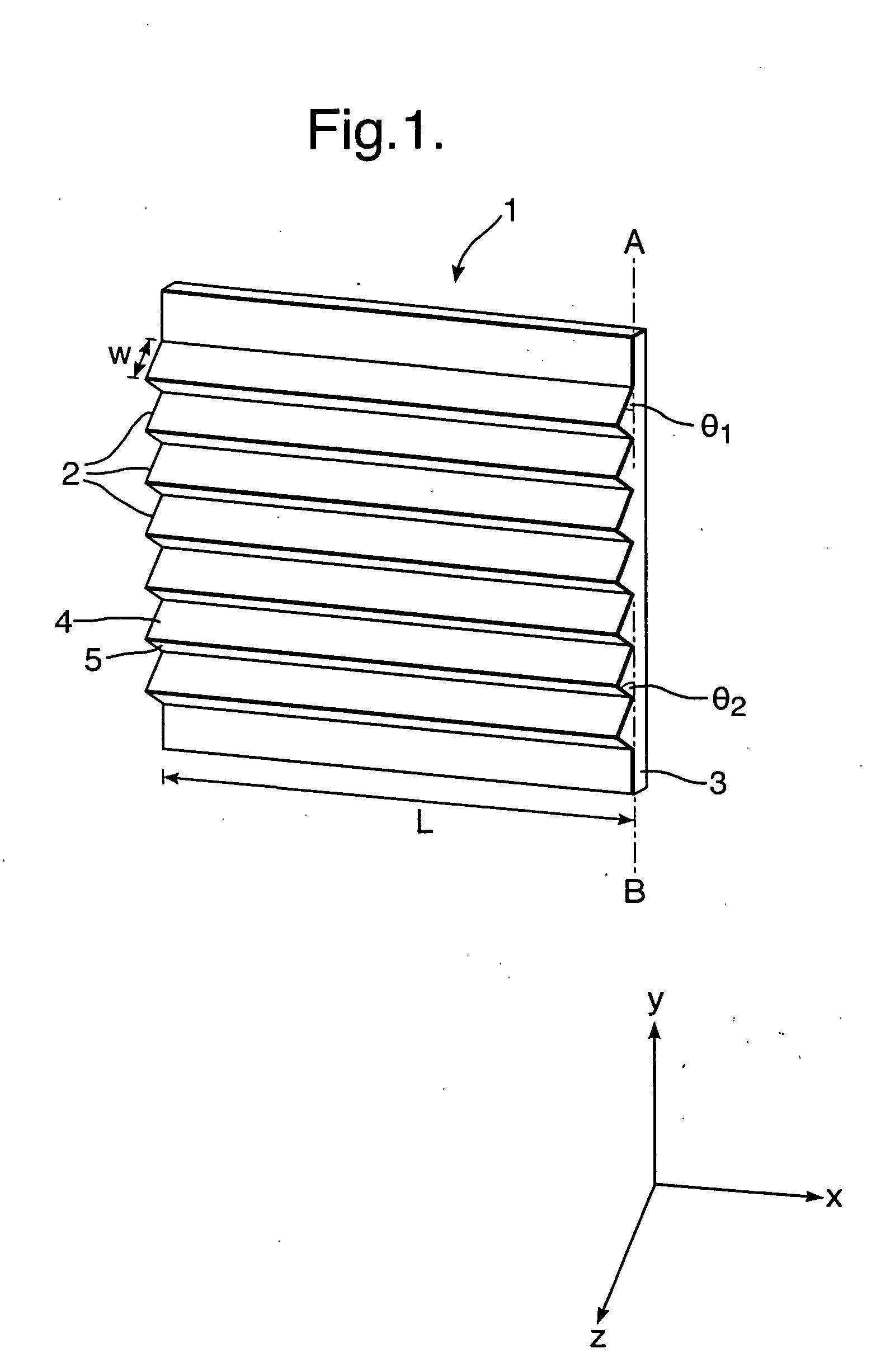
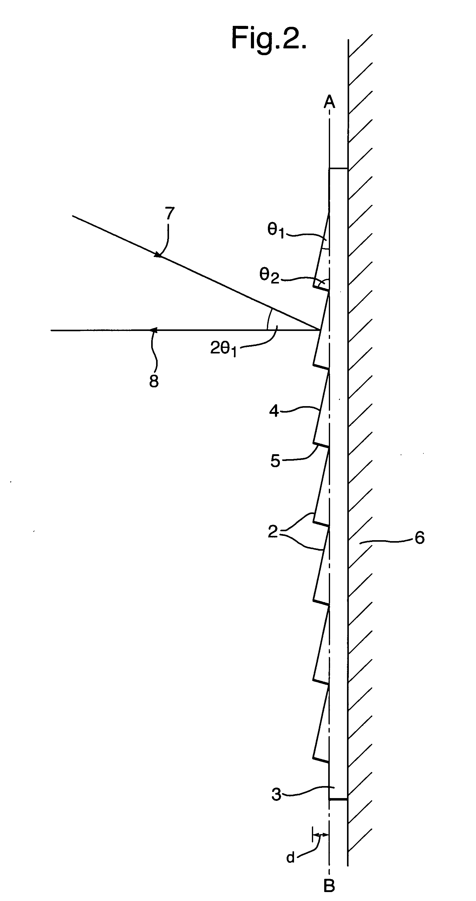
[0082]Four sheets of thermally reflective material were machined from stainless steel, each sheet having a 20°-90°-70° sawtooth texture according to the preferred embodiment illustrated in FIGS. 1 and 2 over an area of 200 mm×200 mm. Although the major facet angle θ1 was 20° for each panel, the depth of the texture, d, and accordingly, the width, w, of the facets, was different in each case; the depths used were 2 mm, 1 mm, 0.5 mm and 0.2 mm. Panels were constructed from the thermally reflective material by cutting the sheet material to size and the panels were mounted vertically on the front of a vehicle. FIG. 7 shows a night-time 8-12 micron thermal infrared image of the vehicle taken using the FLIR imager, demonstrating that the panels worked effectively, that is, intense ‘apparently cold’ areas are visible on the vehicle. There was negligible variation in reflection efficiency between the different facet sizes.

example 2

[0083]A flexible directional reflector material was manufactured by the following method, said material having reflecting elements taking the form of parallel, equal-sized ridges with a triangular cross section (that is, the preferred sawtooth embodiment illustrated in FIGS. 1 and 2). A mould was machined from a titanium block with a repeated pattern of 20°-90°-70° prisms (that is, major facet angle 20° and minor facet angle 70°) with minor facet width 1.06 mm and major facet width, w, 2.92 mm (triangle base length 3.1 mm). The mould surface was replicated by using a filled poly vinyl chloride (PVC) moulding material to form the working mould. Onto the internal surface of the PVC mould, a thin layer of silver was deposited by silver nitrate reduction to form a sacrificial layer to ease removal of the final material from the mould and onto which subsequent layers could be electrodeposited. Onto the silver layer, a 1 micron layer of gold was electroplated and a 100 micron layer of cop...

example 3

[0085]The material of the invention can be ‘overwritten’ using conventional, self-adhesive vehicle sign-writing vinyl to create readable text, graphics or markings in both the visible or thermal infrared.

[0086]A sheet of thin-foil material having a micro-structured, thermally reflective texture was prepared by electro-forming nickel onto a fluorinated polyurethane former having a sawtooth texture according to the preferred embodiment illustrated in FIGS. 4 and 5. The major facet angle θ1 was 10°, and the major facet width, w, was 0.86 mm. The minor facet angle θ2 was 80° and the minor facet width was 0.15 mm. Once the nickel had been grown to a thickness of 100 micron, it was peeled from the pattern former and then electroplated on the working surface with 1 micron of gold. The gold-coated nickel foil was stuck to an aluminium substrate plate (800×400 mm) using a contact adhesive and the thermally reflective material was then overlaid with the letters ‘C’, ‘I’ and ‘D’ cut from self-...


PUM

PropertyMeasurementUnit
thermal emissivityaaaaaaaaaa
wavelengthaaaaaaaaaa
temperatureaaaaaaaaaa

Abstract

A sheet of thermally reflective material (1) has a surface texture comprising a plurality of reflecting elements (2), wherein each element has a first facet (4) which is substantially reflective at thermal infrared wavelengths and wherein the respective first facets (4) form an angle θ with the plane of the sheet (A-B) (0°<θ<90°). Preferably, the first facets (4) are aligned such that, in use, thermal radiation is reflected from a common direction. By orienting the sheet of thermally reflective material to reflect cold regions of the sky, a marking material exhibiting a cold spot in a thermal imager can be provided.

Description

FIELD OF THE INVENTION[0001]The present invention relates to a reflective material and, in particular, to a material which is reflective in the thermal infrared and / or near infrared wavebands. The invention also relates to identification devices incorporating said material and methods for using said materials and devices.BACKGROUND OF THE INVENTION[0002]The invention is particularly, but not exclusively, applicable to vehicles, fixed structures and / or personnel to aid their identification, and is more particularly applicable to the ground-to-ground identification of said objects. The invention enables unambiguous identification using near infrared and / or thermal infrared imaging techniques, either in combination or in isolation. The invention is particularly suitable for use in scenarios where identification markings enable the viewer to differentiate between marked and unmarked vehicles, fixed structures and / or personnel through an electro-optic imaging system.[0003]Infrared imagin...

Claims


Application Information

Patent Timeline
Patent Type & Authority Applications(United States)
IPC IPC(8): G09F3/02B32B33/00B32B3/30B32B3/28
CPCF41H1/02F41H3/00F41H5/00G02B5/045G02B17/002G02B17/006Y10T428/12201G09F13/14G02B19/009G02B19/0028G02B19/0033Y10T428/23Y10T428/24116G09F3/02
Inventor O'KEEFE, EOIN S.SHOHET, ADAM J.SWAN, MARTIN
Owner QINETIQ LTD
Why Eureka
Try Eureka