Vehicle air-conditioning apparatus

a technology for air conditioning apparatus and vehicles, which is applied in the direction of lighting and heating apparatus, domestic cooling apparatus, defrosting, etc., can solve the problems of increasing the inability to set the temperature of the heat transfer medium, and the increase of the power consumption of the primary circulation channel of the heat pump, so as to achieve the effect of minimizing the power consumption of the refrigeration cycle system

Active Publication Date: 2014-05-27
HITACHI LTD
View PDF8 Cites 10 Cited by
  • Summary
  • Abstract
  • Description
  • Claims
  • Application Information

AI Technical Summary

Benefits of technology

[0007]However, in the cooling system for a vehicle disclosed in JP 2005-273998 A1, the heat-transfer medium for cooling in the secondary circulation channel flows from the air-conditioning heat-exchanger to the heat-liberation components set up on the vehicle, so that the heat-transfer medium could not be set at temperatures that are most suitable for air-conditioning in the vehicle interior and for cooling the heat-liberation components, respectively, simultaneously. For example, when it is required to cool the heat-transfer medium to about 10° C. for cooling the vehicle interior, the heat-transfer medium that is circulated through the in-vehicle heat-liberation components is to be cooled to about 10° C. If the temperature of an in-vehicle heat-liberation component becomes lower than a temperature of an outside air, heat flows in from the outside air to the in-vehicle heat-liberation component. The refrigeration system needs to perform extra cooling corresponding to the amount of heat that flew in. This increases power consumption by the refrigeration cycle system.
[0008]On the other hand, the air-conditioning system for a vehicle disclosed in JP 2008-230594 A1 has a construction such that the heat-transfer medium in the secondary circulation channel is heated by using an intermediate heat-exchanger and a heater in combination. In this construction, the temperature at which condensation occurs in the intermediate heat-exchanger is influenced by the temperature of the heat-transfer medium therein. When the heater is used, the temperature of the heat-transfer medium increases, so that the temperature at which refrigeration is performed by the intermediate heat-exchanger increases, resulting in that the power consumption by the primary circulation channel of the heat pump increases in order to get the same performance of air heating. In other words, the power consumption for the primary circulation channel of the heat pump as well as the power consumption by the heater increases.
[0012]According to a fourth aspect, the invention provides a moving vehicle air-conditioning apparatus according to the first aspect, wherein the air-conditioning heat-exchange circuit is connected to the expansion valve through an air-conditioning expansion valve that reduces pressure of the refrigerant, and the cooling heat-exchanger in the cooling heat-transfer medium circulation channel is connected to the expansion valve through a cooling expansion valve that reduces pressure of the refrigerant.
[0029]According to the present invention, the temperatures of cooling media that flow in a heat-exchange circuit for air-conditioning and a heat-exchange circuit for in-vehicle equipment can be set at most suitable temperatures, respectively, so that the power consumption by the refrigeration cycle system can be minimized.

Problems solved by technology

However, in the cooling system for a vehicle disclosed in JP 2005-273998 A1, the heat-transfer medium for cooling in the secondary circulation channel flows from the air-conditioning heat-exchanger to the heat-liberation components set up on the vehicle, so that the heat-transfer medium could not be set at temperatures that are most suitable for air-conditioning in the vehicle interior and for cooling the heat-liberation components, respectively, simultaneously.
This increases power consumption by the refrigeration cycle system.
In other words, the power consumption for the primary circulation channel of the heat pump as well as the power consumption by the heater increases.

Method used


Image

  • Vehicle air-conditioning apparatus
  • Vehicle air-conditioning apparatus
  • Vehicle air-conditioning apparatus

Examples


first embodiment

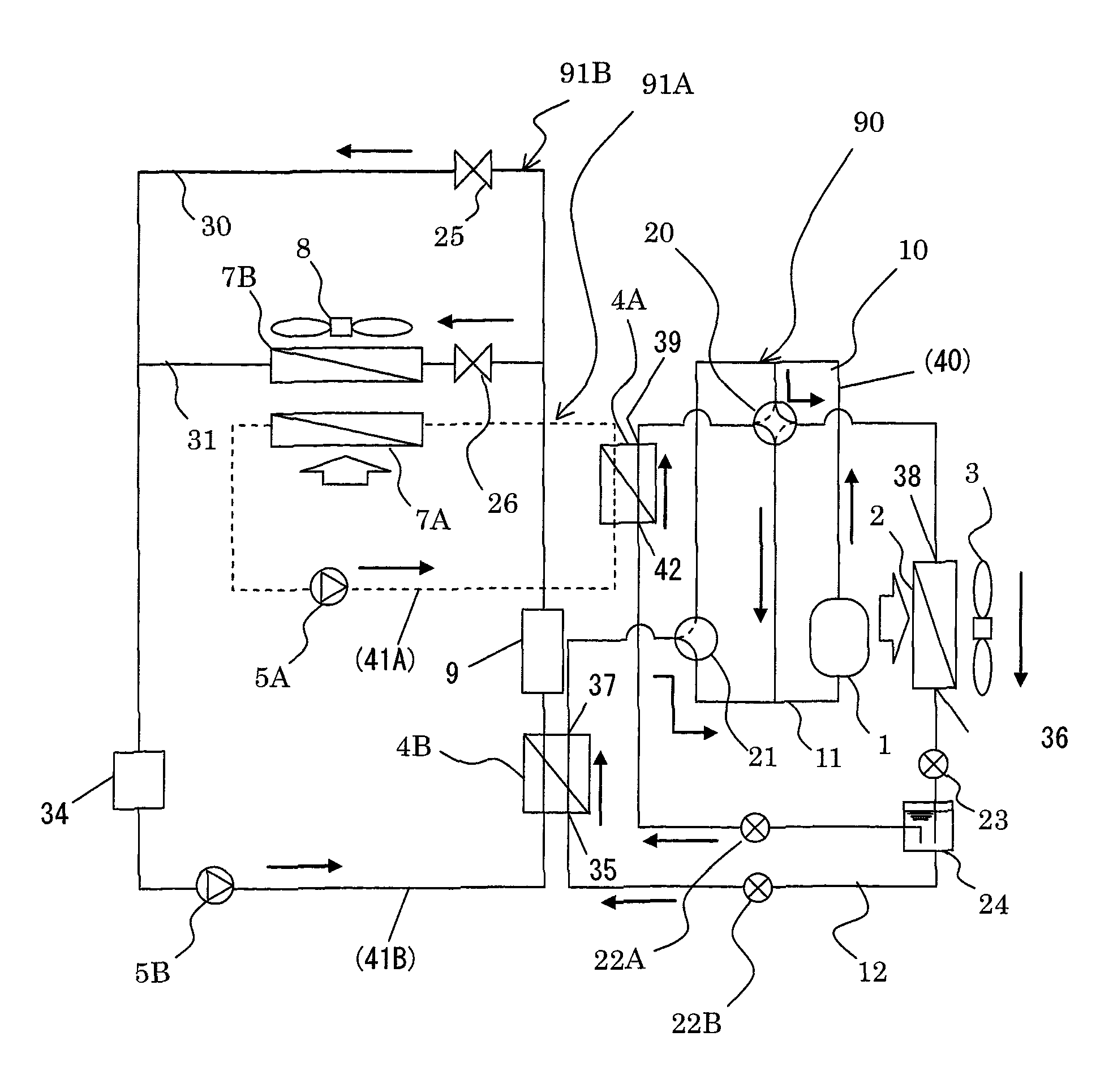
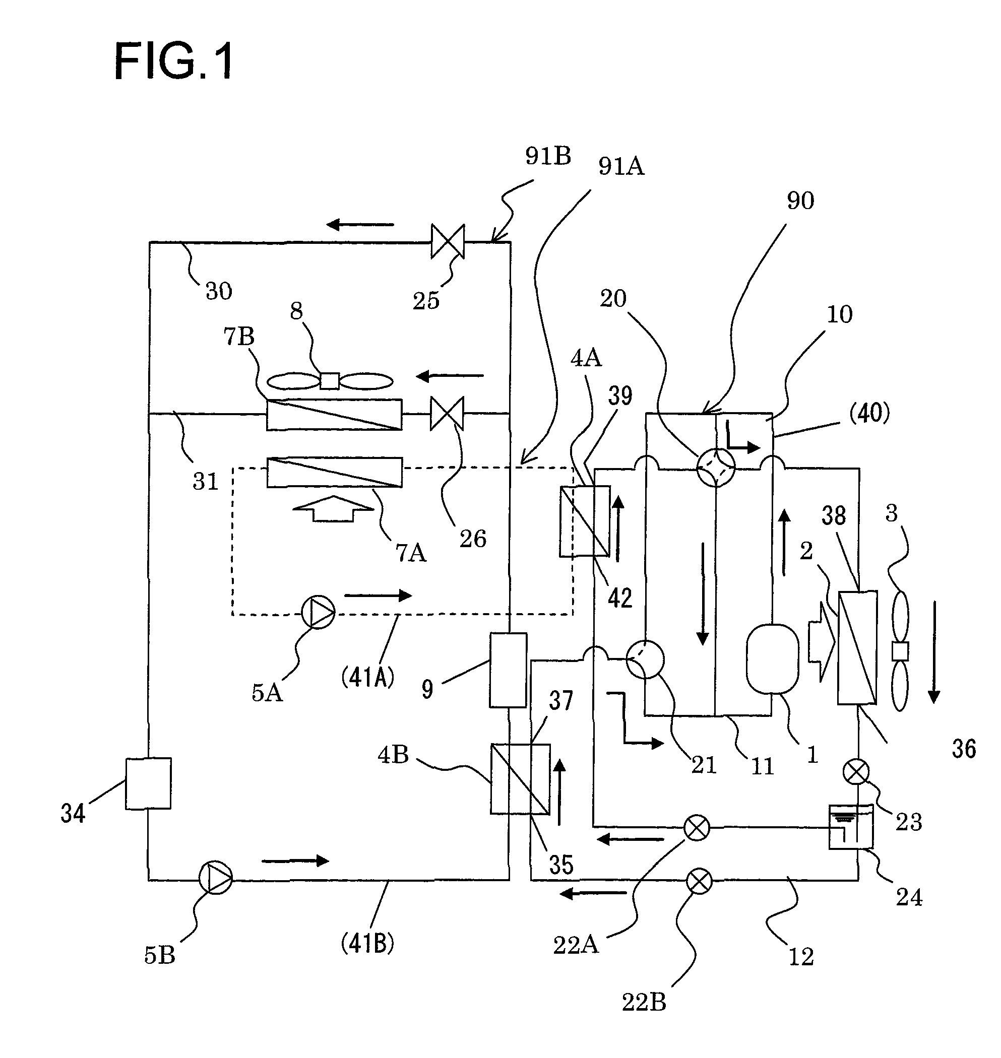
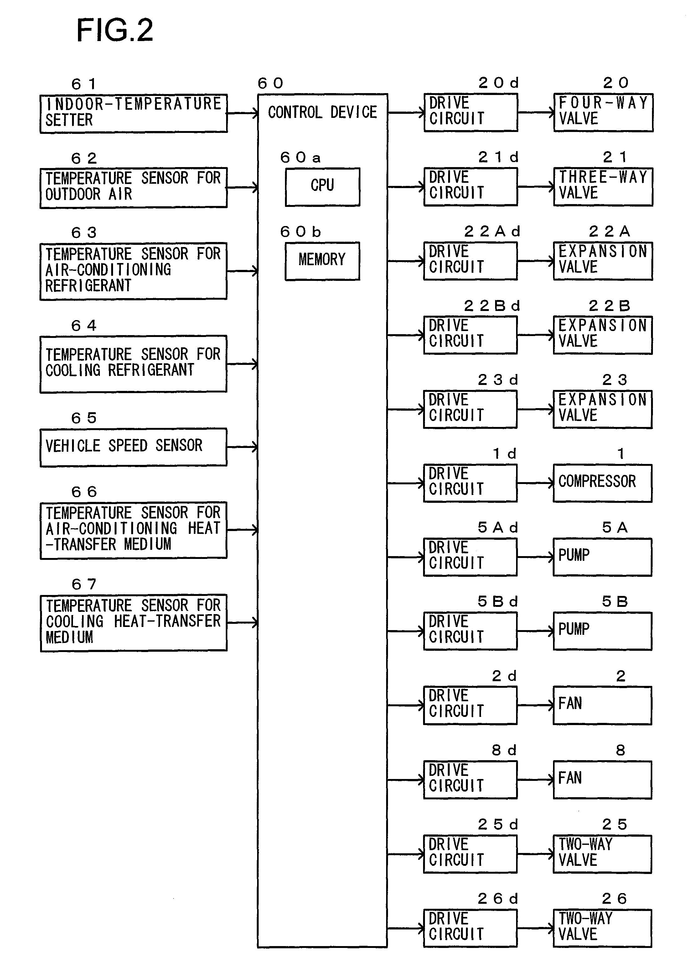
[0045]FIG. 1 presents a schematic diagram showing a construction of a vehicle air-conditioning apparatus according to a first embodiment of the present invention. FIG. 2 presents a block diagram showing an electric circuit of a vehicle air-conditioning apparatus according to the first embodiment of the present invention. The vehicle air-conditioning apparatus 1 according to the first embodiment comprises three heat-transfer medium circulation channels. More particularly, a first one is a cooling medium (or refrigerant) circulation channel (or primary circulation channel) 90 of a refrigeration cycle system, which performs compression, condensation, expansion and evaporation of a refrigerant 40. A second one is a heat-transfer medium circulation channel for air-conditioning (hereafter, air-conditioning heat-transfer medium circulation channel) (or secondary circulation channel A) 91A, which is connected to the refrigerant circulation channel 90 of the refrigeration cycle system (herea...

second embodiment

[0106]FIG. 10 presents a schematic diagram showing a construction of a vehicle air-conditioning apparatus according to a second embodiment of the present invention. This diagram illustrates the flow of the refrigerant upon cooling operation. Apparatuses and components that are the same as or similar to those explained with reference to FIGS. 1 to 9 are given the same reference numbers and explanation thereon is focused on differences between the first and the second embodiments. In the second embodiment, the three-way valve 21 used in the first embodiment as shown in FIGS. 1 to 9 is not used and the outlet / inlet 37 of the cooling heat-exchanger 4B is connected to the intake pipe 11 of the compressor 1. An electric circuit according to the second embodiment is the same as the electric circuit used in the first embodiment as shown in FIG. 2 except that the three-way valve 21 and the drive circuit 21d are omitted. Therefore, illustration and explanation of the electric circuit is omitt...

third embodiment

Variations of Third Embodiment

[0113]The apparatus according to the third embodiment shown in FIG. 11 includes the radiator 50 in parallel to the indoor heat-exchanger 7B in the cooling heat-transfer medium circulation channel 91B. However, the radiator 50 may be provided in series to the indoor heat-exchanger 7B as shown in FIG. 13. By the addition of the radiator 50, that release to the outside air can be performed without resort to the refrigeration cycle system refrigerant circulation channel 90. For example, when the load of heating for heating the vehicle interior is decreased while the heating-heat releasing operation is performed, the amount of heat released to the vehicle interior is decreased so that heat release cannot be accomplished completely. In this case, the state of deficient capability of heat release can be solved by releasing heat to the outside air by means of the radiator 50. If there is yet a deficiency in the capability of heat release even when heat release ...


PUM


Abstract

A vehicle air-conditioning apparatus, including: a refrigerant circulation channel that flows a refrigerant, the refrigerant circulation channel provided in a refrigeration cycle system including, as connected in a cyclic pattern, a compressor for the refrigerant, an outdoor heat-exchanger exchanging heat between the refrigerant and an outdoor air, an expansion valve reducing pressure of the refrigerant, and an air-conditioning heat-exchange circuit exchanging heat between the refrigerant and air to be introduced into a vehicle interior; and an equipment heat-exchange circuit connected in parallel to the circuit and exchanging heat between the refrigerant and in-vehicle equipment. The circuit includes a cooling heat-transfer medium circulation channel that circulates a heat-transfer medium for cooling. The cooling channel has a cooling heat-exchanger exchanging heat between the refrigerant in the channel and a cooling heat-transfer medium for cooling the in-vehicle equipment and a cooling circulation pump for circulating the cooling heat-transfer medium.

Description

INCORPORATION BY REFERENCE[0001]The disclosure of the following priority application is herein incorporated by reference: Japanese Patent Application No. 2009-262528 filed Nov. 18, 2009.BACKGROUND OF THE INVENTION[0002]1. Field of the Invention[0003]The present invention relates to a vehicle air-conditioning apparatus, i.e., an air-conditioning apparatus for use in a vehicle.[0004]2. Description of Related Art[0005]There have been known technologies concerning a cooling system for a vehicle comprising a primary circulation channel and a secondary circulation channel. The secondary circulation channel circulates heat-transfer medium through a vehicle interior (i.e., indoor) air-conditioning heat-exchanger and in-vehicle devices or components (i.e., equipment set up on the vehicle) to perform air-conditioning and cool the equipment set up on the vehicle. The primary circulation channel for a refrigeration cycle system exchanges heat with the heat-transfer medium in the secondary circu...

Claims


Application Information

Patent Timeline
Patent Type & Authority Patents(United States)
IPC IPC(8): B60H3/00F25B41/04F25B1/00F25B41/00B60H1/32
CPCB60H1/00278B60H1/00907B60H2001/00928B60L1/003B60L1/02B60L2240/12B60L2240/34B60L2240/36B60L2240/662B60H2001/00307B60H2001/00935B60H1/32281B60H2001/00961Y02T10/72Y02T90/16
Inventor SEKIYA, SACHIOOSAKA, TADASHISAWADA, ITSUROIMANISHI, YUTO
Owner HITACHI LTD
Why Eureka
Try Eureka