Parallel shaft transmission

a transmission shaft and parallel shaft technology, applied in mechanical equipment, transportation and packaging, gearing, etc., can solve the problems of difficult to achieve a sufficient size reduction in the axial direction, and the transmission is designed to occupy a limited amount of space, and achieve the effect of compact structure and small dimension

Inactive Publication Date: 2006-07-25
HONDA MOTOR CO LTD
View PDF11 Cites 14 Cited by
  • Summary
  • Abstract
  • Description
  • Claims
  • Application Information

AI Technical Summary

Benefits of technology

[0016]Even though the parallel shaft transmission according to the present invention achieves a plurality of speed change ratios for forward drive as described above, the size of the transmission in its axial direction is relatively small because the gear (output-shaft first gear) provided on the output shaft to rotate the output shaft in the forward direction in the first speed change condition is used commonly to rotate the output shaft in the forward direction also in the second speed change condition and in the third speed change condition. In short, this specific gear is a commonly used gear. In this way, the number of the gears to be provided on the output shaft is kept relatively small even though the transmission is equipped with this large number of forward speed change ratios. As a result, the transmission according to the present invention achieves a compact design notwithstanding the large number of speed change ratios. In addition, because the first countershaft and the second countershaft are provided radially one over the other, the number of the parts used for the transmission is kept smaller than otherwise, and the space for the installation of the shafts is also economized. As a result, the transmission according to the present invention achieves a design that is effective in reducing the weight as well as the manufacturing cost of the transmission.
[0018]In the parallel shaft transmission, the gear provided on the input shaft to rotate the second countershaft can be used commonly to rotate the intermediary shaft. This arrangement contributes to the reduction of the size of the transmission in its axial direction.
[0019]Attention is given to the above mentioned arrangement where the intermediary shaft second gear is provided rotatably on the intermediary shaft, and the power-switching means includes fifth clutching means, which connects or disconnects the intermediary shaft second gear to or from the intermediary shaft, and where the transmission further comprises an input-shaft fourth gear, which is provided rotatably on the input shaft, sixth clutching means, which connects or disconnects the input-shaft fourth gear to or from the input shaft, an intermediary shaft third gear, which is provided rotatably on the intermediary shaft, seventh clutching means, which connects or disconnects the intermediary shaft third gear to or from the intermediary shaft, and an output-shaft second gear, which is provided on the output shaft to mesh with the input-shaft fourth gear and with the intermediary shaft third gear. In this arrangement, the gear (output-shaft second gear) provided on the output shaft to rotate the output shaft in the forward direction in the fifth speed change condition is used commonly to rotate the output shaft in the forward direction also in the sixth speed change condition. In this arrangement, the size of the transmission in its axial direction increases by the degree of only one gear for the increase of two additional speed change ratios for forward drive. Therefore, the size of the transmission in its axial direction is relatively small notwithstanding the large number of speed change ratios.
[0020]Also, attention is given to the above mentioned arrangement where the parallel shaft transmission further comprises a second countershaft third gear, which is provided rotatably on the second countershaft, a second idle shaft, which is disposed in parallel with the input shaft, a second idle gear, which is provided on the second idle shaft to mesh with the second countershaft third gear and with the input-shaft fourth gear, and eighth clutching means, which connects or disconnects the second countershaft third gear to or from the second countershaft. In this arrangement, the gear (output-shaft second gear) provided on the output shaft to rotate the output shaft in the forward direction in the fifth speed change condition is used commonly to rotate the output shaft in the forward direction in the sixth speed change condition and also to rotate the output shaft in the reversed rotational direction in the seventh speed change condition. In this way, the transmission is equipped with a reverse speed change ratio without any increase in the size of the transmission in its axial direction.
[0021]In the above described parallel shaft transmission, because the second countershaft second gear and the second countershaft third gear are never connected simultaneously to the second countershaft, the fourth clutching means and the eighth clutching means can comprise one selective clutching means, which connects either the second countershaft second gear or the second countershaft third gear to the second countershaft. This arrangement can further improve the lightness and compactness of the transmission.
[0022]Also, attention is given to the above mentioned arrangement where the intermediary shaft is formed in a hollow figure, and an auxiliary intermediary shaft is provided internally, coaxially and rotatably with respect to the intermediary shaft, and where the transmission further comprises ninth clutching means, which connects or disconnects the auxiliary intermediary shaft to or from the intermediary shaft, an auxiliary intermediary shaft gear, which is provided on the auxiliary intermediary shaft, and an output-shaft third gear, which is provided on the output shaft to mesh with the auxiliary intermediary shaft gear. In this arrangement, these shafts (i.e., the intermediary shaft and the auxiliary intermediary shaft) are disposed radially one over the other. This arrangement enables the transmission to acquire one additional speed change ratio for forward drive with an addition of only a few more parts.

Problems solved by technology

However, transmissions are designed to occupy certain limited amounts of space in specific machines or equipment in which they are intended to be installed.
However, for recently developed transmissions with large numbers of speed change ratios, it is difficult to achieve a sufficient size reduction in axial direction by the above described structural arrangement in which a gear provided on the output shaft is used commonly for achieving two different speed change ratios.

Method used


Image

  • Parallel shaft transmission
  • Parallel shaft transmission
  • Parallel shaft transmission

Examples


first embodiment

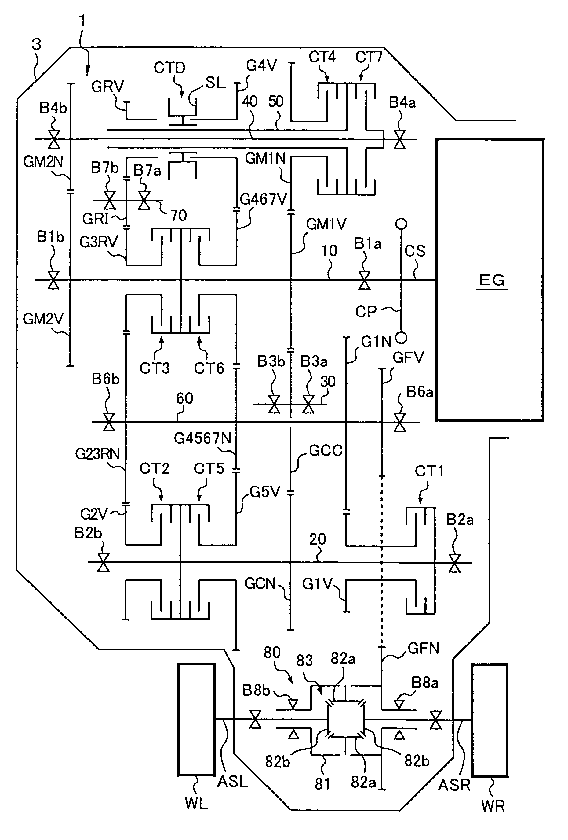
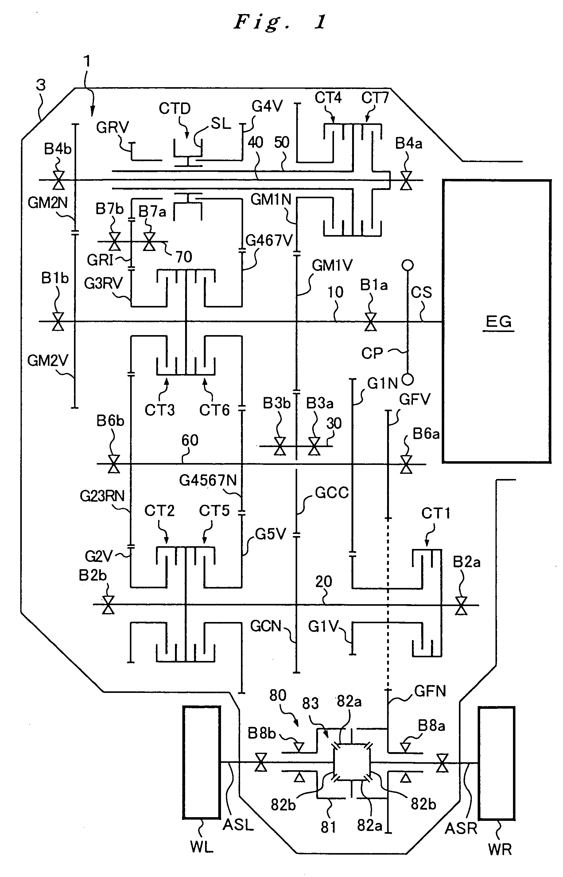
[0049]In the transmission 1 as a first embodiment, which achieves seven forward speed change ratios and one reverse speed change ratio as described above, the gear (fourth, fifth, sixth and seventh speed driven gear G4567N) provided on the output shaft 60 to rotate the output shaft 60 in the forward direction in the forward fourth speed condition is used commonly to rotate the output shaft 60 in the forward direction also in the forward fifth speed condition, in the forward sixth speed condition and in the forward seventh speed condition. In short, this specific gear is a commonly used gear. In this way, the number of the gears to be provided on the output shaft 60 for achieving this large number of forward speed change ratios is kept relatively small. As a result, the size of the transmission 1 in its axial direction is relatively small, so the transmission 1 has a compact design.

[0050]Furthermore, in the transmission 1, the second and third speed and reverse driven gear G23RN is p...

second embodiment

[0055]To switch the transmission 1′ as a second embodiment from the forward seventh speed condition to a forward eighth speed condition, the seventh speed clutch CT7 is turned from “ON” to “OFF”, and the eighth speed clutch CT8 is turned from “OFF” to “ON”. As a result, the first countershaft 40 and the second countershaft 50 are disconnected from each other while the intermediary shaft 20′ and the auxiliary intermediary shaft 25 are connected to each other. In this condition, or the forward eighth speed condition of the transmission 1′, the power of the engine EG, which is transmitted from the input shaft 10 through the first main drive gear GM1V, the connecting idle gear GCC and the connecting driven gear GCN to the intermediary shaft 20′, is transmitted by the eighth speed clutch CT8 to the auxiliary intermediary shaft 25 and then through the eighth speed drive gear G8V and the eighth speed driven gear G8N to the output shaft 60.

[0056]In the above described ways, the transmission...


PUM


Abstract

An input shaft 10 is connected rotationally with a first countershaft 40 through a second main drive gear GM2V and a second main driven gear GM2N, and a second countershaft 50 is provided externally, coaxially and rotatably with respect to the first countershaft 40. A first main drive gear GM1V which is provided on the input shaft 10, always meshes with a first main driven gear GM1N, which is provided rotatably over the second countershaft 50. A fourth, sixth and seventh speed drive gear G467V, which is provided rotatably over the input shaft 10, always meshes both with a fourth speed drive gear G4V, which is provided rotatably over the second countershaft 50, and with a fourth, fifth, sixth and seventh speed driven gear G4567N, which is provided on the output shaft 60.

Description

FIELD OF THE INVENTION[0001]The present invention relates to a parallel shaft transmission, in which gears are provided over a plurality of shafts disposed in parallel with one another, the gears being meshed in pairs so that the engagement and disengagement of gears to corresponding ones of the shafts establishes a power transmission path through the shafts in engagement to achieve a desirable speed change ratio, which corresponds to a momentary gear ratio of the transmission.BACKGROUND OF THE INVENTION[0002]Such parallel shaft transmissions are used in various powered machines including automobiles. In recent years, there has been a tendency that transmissions for use in vehicles are equipped with increasing numbers of speed change ratios because of demands for improvements in driving performance and of concerns on environmental effect. As a result, some transmissions that have more than five speed change ratios for forward drive have been developed for practical use. Generally, a...

Claims


Application Information

Patent Timeline
Patent Type & Authority Patents(United States)
IPC IPC(8): F16H3/08F16H3/093
CPCF16H3/093F16H2003/0938F16H2200/0056Y10T74/19219Y10T74/19233Y10T74/19223Y10T74/19228F16H2200/006
Inventor HATAKEYAMA, KAZUMA
Owner HONDA MOTOR CO LTD
Why Eureka
Try Eureka