Screwdriver tool

a screwdriver and tool technology, applied in screwdrivers, wrenches, slip couplings, etc., can solve the problem that the spring element no longer holds the tool shank in a non-rotatable manner in the driving body, and achieves the effect of simple and cost-effective assembly

Inactive Publication Date: 2006-07-25
WIHA WERKZEUGE
View PDF17 Cites 31 Cited by
  • Summary
  • Abstract
  • Description
  • Claims
  • Application Information

AI Technical Summary

Benefits of technology

[0007]Employing a spring-elastic ring as a spring element surrounding the tool shank increases the outer diameter of the tool shank only a little, enabling an extremely compact arrangement in the handle of a screwdriver tool. Therefore, the torque limiter is particularly well-suited for fine screwdrivers such as screwdrivers having a key-type handle or a flat handle. The suitability of the torque limiter for such small screwdriver tools also results from the fact that the torque limiter according to the present invention may allow for low limiting torques.
[0008]The torque limiter is particularly cost-effective if the spring element is a plastic spring. If the spring force of a plastic spring is insufficient, the spring force may be increased by a spring metal insert. It is also possible to introduce wear-resistant inserts into the plastic material in those areas where the spring element is in contact with the clutch section to prevent erosion of the plastic material.
[0009]The spring element may be adjusted to the cross section of the clutch section in such a way that the spring element is not radially deflected if it is adjacent to the area of the periphery of the clutch section having the smallest radius. Therefore, in the resting state, when the screwdriver tool is not in use, no force is applied to the spring element, which would be deflected in response to the stress. Material fatigue of the spring element may thus be avoided. This is advantageous when the spring element is made of plastic because a permanent load on the plastic material over an extended period may cause the plastic material to creep, changing the shape and elastic properties of the spring element.
[0011]The torque limiter described herein allows for simple and cost-effective assembly. In one embodiment, a spring element designed as a ring is inserted into a blind hole of the handle, which is coaxially traversed by the tool shank and closed by a handle cover.

Problems solved by technology

If this limiting torque is exceeded, the spring element no longer holds the tool shank in a non-rotatable manner in the driving body.

Method used


Image

  • Screwdriver tool
  • Screwdriver tool
  • Screwdriver tool

Examples


Embodiment Construction

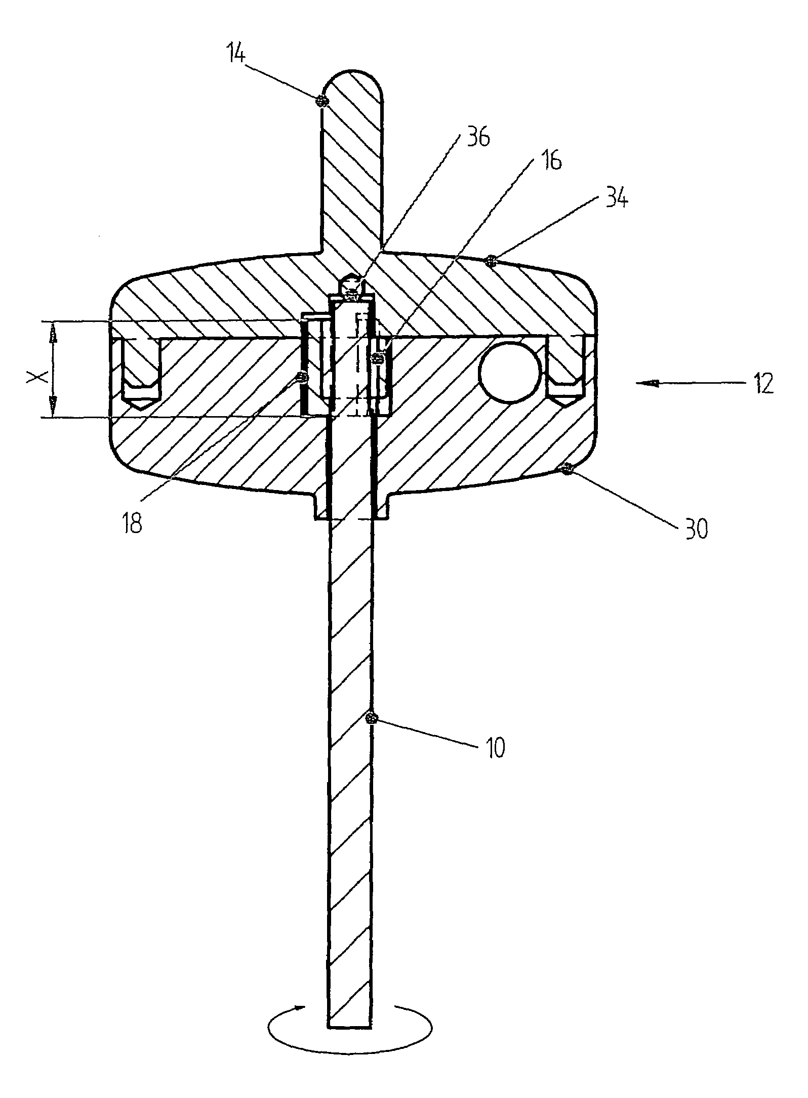
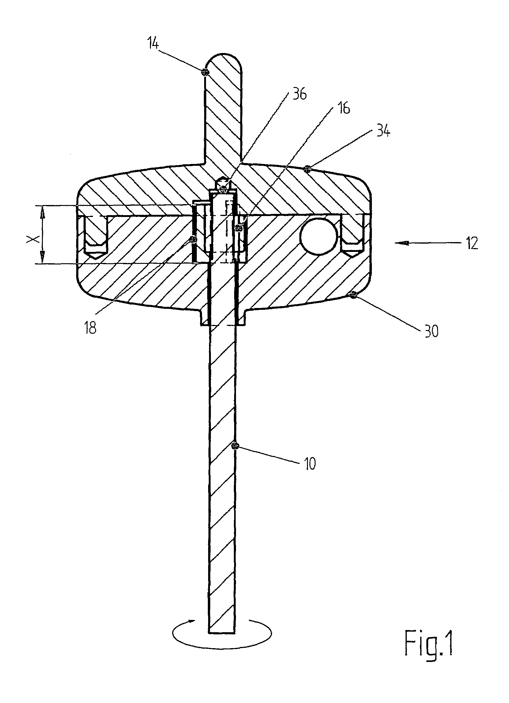
[0015]In FIG. 1, an exemplary torque limiter is described with reference to a screwdriver tool having a key-type handle. One skilled in the art will recognize that other types of screwdrivers and handles may benefit from the teachings herein.

[0016]The screwdriver includes a tool shank 10 made of steel, the front end of which is designed as a working end (not illustrated). The rear end of tool shank 10 is inserted into a handle 12, which may be made of plastic. Handle 12 is a key-type handle and has the shape of a flat transverse handle having a support pin 14, which is formed in the axially flush extension of tool shank 10 on the rear end of handle 12.

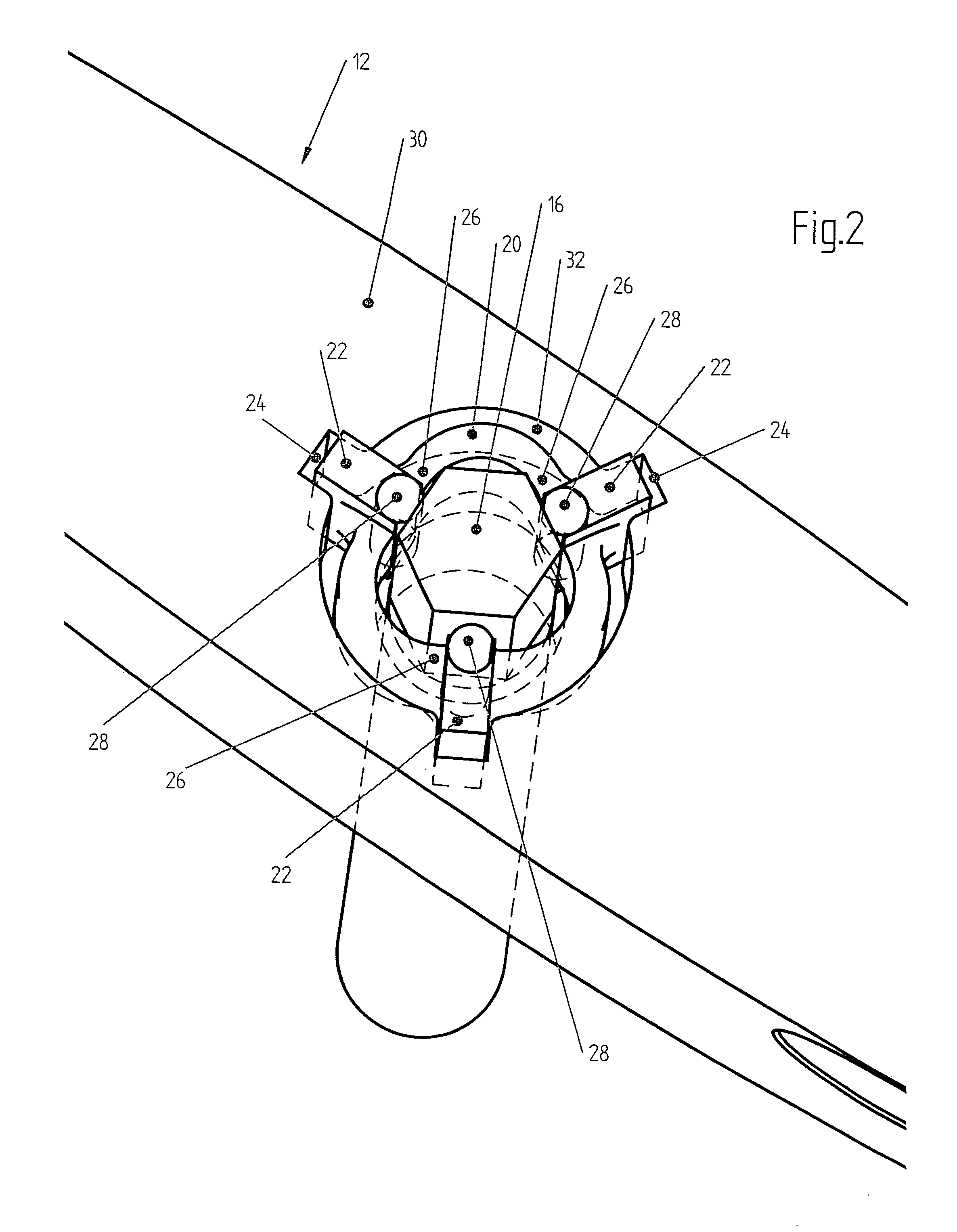
[0017]The rear end of tool shank 10 is rotatably disposed in a bore hole of handle 12. At least in the end region accommodated in handle 12, tool shank 10 is fabricated as a clutch section 16 having a non-circular cross section. This non-circular cross section may be a polygonal cross section, for example, a hexagonal cross section. A ...


PUM


Abstract

A screwdriver tool has a driving body and a tool shank mounted in the driving body so it can rotate about its axis. A device for transmitting a torque from the driving body to the tool shank interrupts the torque transmission if a predefined limiting torque is exceeded. In its longitudinal area accommodated in the driving body, the tool shaft has a clutch section featuring a non-circular cross section. At least one spring element adjoins the clutch section radially on the outside. The spring element is mounted in the driving body in a non-rotatable manner with respect to the axis of the tool shank and in a radially deflectable manner against its spring force.

Description

FIELD OF THE INVENTION[0001]The present invention relates to a screwdriver tool.BACKGROUND OF THE INVENTION[0002]Screwdriver tools equipped with a torque limiter are known. Such a screwdriver tool permits a torque to be applied to a part to be driven, for example, a screw. If the torque exceeds a predefined limiting torque, e.g., the specified tightening torque of a screw, the torque transmission is interrupted.[0003]DE 101 43 181 A1 describes such a screwdriver in which the torque limiter is mounted in the handle. Torque is limited via a clutch whose parts are held engaged by a helical pressure spring and are disengaged against the force of the helical spring in the event the limiting torque is exceeded. The clutch and the helical pressure spring acting on the clutch require so much space that this torque limiter can only be used with bulkier handles.[0004]Thus, it would be desirable to have a screwdriver tool in which the torque limiter has a compact, simple, and cost-effective de...

Claims


Application Information

Patent Timeline
Patent Type & Authority Patents(United States)
IPC IPC(8): B25B23/159B25B23/14B25B23/16B25B23/142B25B23/157F16D7/10
CPCB25B23/141F16D7/10B25B23/1427
Inventor KARLE, OTMAR
Owner WIHA WERKZEUGE
Why Eureka
Try Eureka