Emergency brake apparatus of elevator

a technology for emergency braking and elevators, which is applied in the direction of mechanically actuated brakes, elevators, thin material handling, etc. it can solve the problems of increasing the overall size and expense of the elevator, the difficulty of releasing the braking force, and the mechanical shock of the collision may not be buffered sufficiently, so as to reduce the overall size.

Inactive Publication Date: 2006-07-25
MITSUBISHI ELECTRIC CORP
View PDF20 Cites 33 Cited by
  • Summary
  • Abstract
  • Description
  • Claims
  • Application Information

AI Technical Summary

Benefits of technology

[0005]The present invention aims to solve the above problems and an object of the present invention is to provide an elevator emergency braking apparatus enabling overall size to be reduced.

Problems solved by technology

However, if the counterweight collides with the counterweight buffer at a faster speed than a design velocity, the mechanical shock from the collision may not be buffered sufficiently.
However, in such methods, it is necessary for space to be secured for installing a speed governor for detecting the speed of the counterweight, and for the safeties for the counterweight, etc., increasing the overall size and expense of the elevator.
Braking apparatuses for stopping the car and the counterweight by gripping a main rope suspending the car and the counterweight have also been proposed, but in braking apparatuses of this type, mechanisms for generating a braking force are large, and constructions for releasing the braking force are complicated, making the machinery expensive.

Method used


Image

  • Emergency brake apparatus of elevator
  • Emergency brake apparatus of elevator
  • Emergency brake apparatus of elevator

Examples


embodiment 1

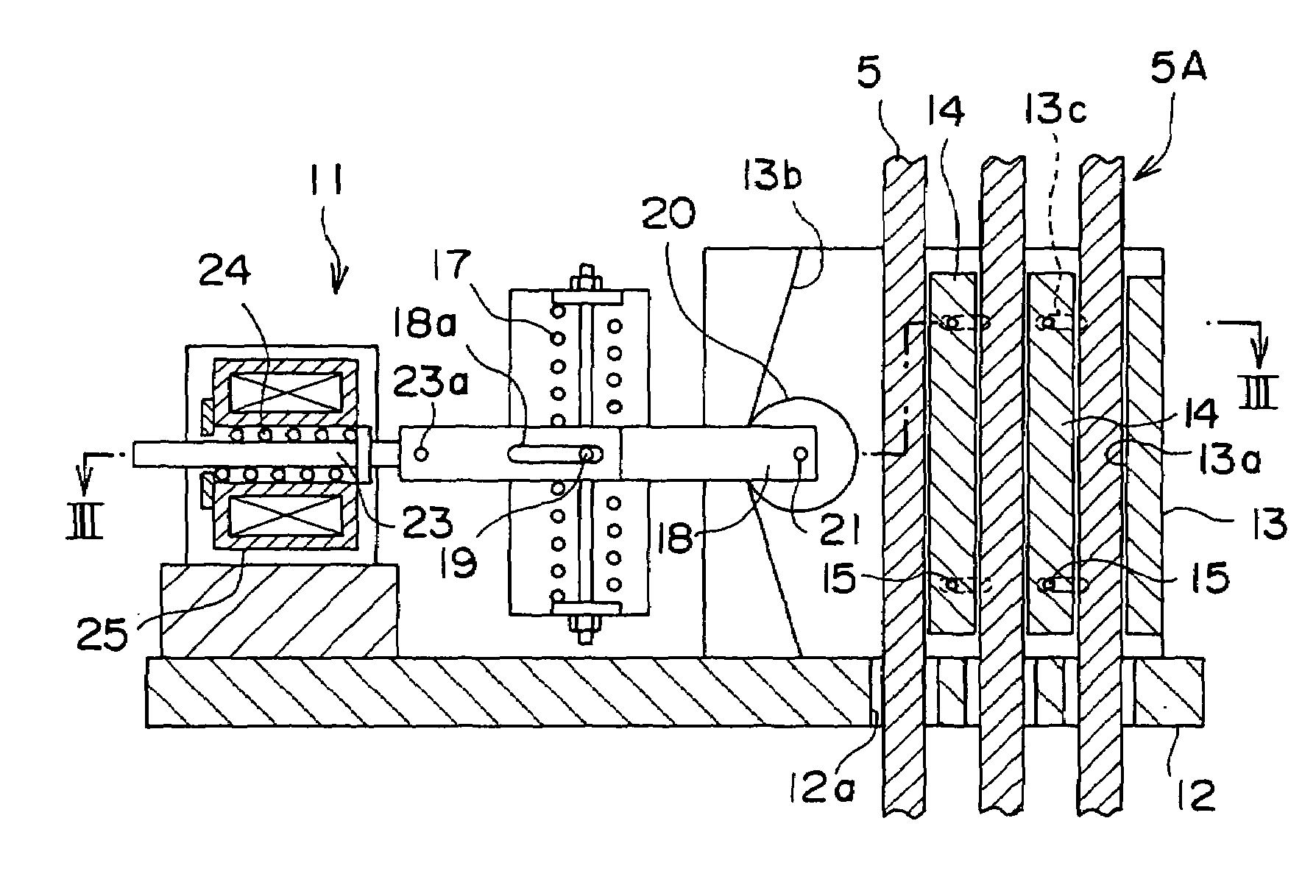
[0018]FIG. 1 is a schematic structural diagram showing an elevator according to Embodiment 1 of the present invention. In the figure, a machine room 2 is disposed in an upper portion of a hoistway 1. A machine base 10 is installed inside the machine room 2. A driving apparatus 3 having a drive sheave 3a, and a deflection sheave 4 are supported on the machine base 10. A plurality of main ropes 5 (only one is shown in FIG. 1) are wound over the drive sheave 3a and the deflection sheave 4.

[0019]A car 6 is suspended by first end portions of the main ropes 5. A counterweight 7 is suspended by second end portions of the main ropes 5. The car 6 and the counterweight 7 are raised and lowered inside the hoistway 1 by a driving force from the driving machine 3. A pair of car guide rails 8 for guiding raising and lowering of the car 6, and a pair of counterweight guide rails 9 for guiding raising and lowering of the counterweight 7 are installed inside the hoistway 1.

[0020]An emergency braking...

embodiment 2

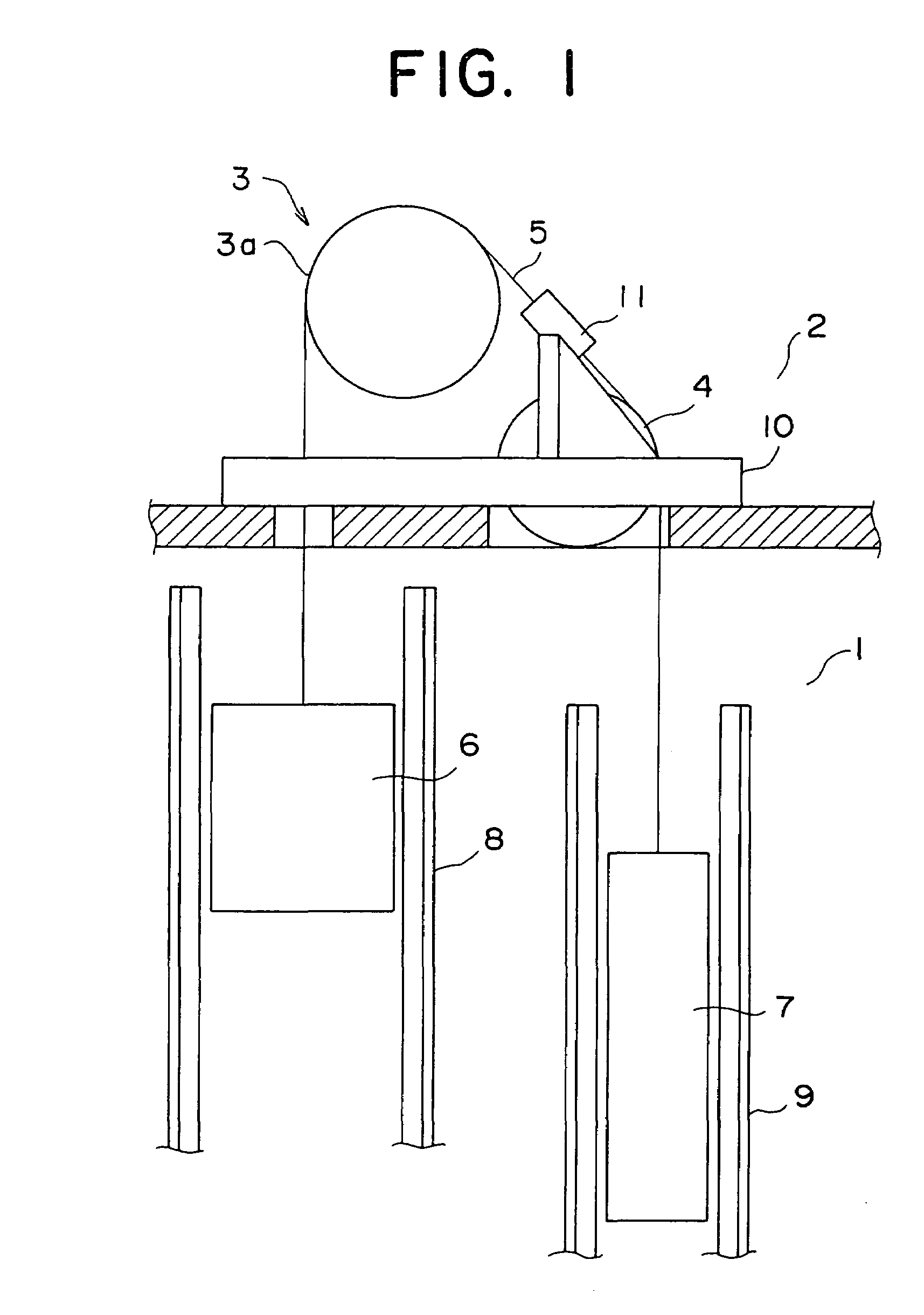
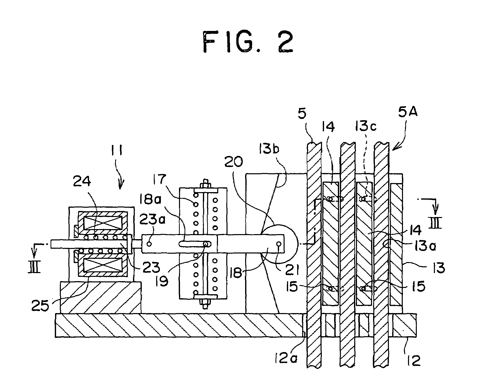
[0044]FIG. 7 is a cross section showing a state of an emergency braking apparatus according to Embodiment 2 of the present invention during normal operation, FIG. 8 is a cross section taken along line VIII—VIII in FIG. 7, FIG. 9 is a cross section showing a state of the emergency braking apparatus in FIG. 7 during braking, and FIG. 10 is a cross section taken along line X—X in FIG. 9. Moreover, FIG. 7 is a cross section taken along line VII—VII in FIG. 8.

[0045]In the figures, a wedge member 31 swingable around a shaft 21 is supported on a tip portion of a movable arm 18. A braking device main body 13 has: a braking plate 32 functioning as a braking member; and a plurality of braking plate supporting springs 33 functioning as an elastic body for supporting the braking plate 32. The braking plate 32 has a main body braking surface 13a facing a main rope 5 positioned at a first side portion of a main rope array 5A. An amount of compression in the braking plate supporting springs 33 is ...


PUM


Abstract

In an elevator emergency braking apparatus, a braking device main body has a main body braking surface facing a main rope and positioned at a first side of a main rope array, and a tapered surface facing the main body braking surface on an opposite side of the main rope array. An intermediate braking piece is disposed between mutually-adjacent main ropes inside the braking device main body. The intermediate braking piece is displaceable in a direction to be placed separably in contact with the main body braking surface. A wedge member is disposed between the tapered surface and the main rope array. The wedge member is separated from the main ropes during normal operation, and wedged between the tapered surface and the main ropes during braking.

Description

TECHNICAL FIELD[0001]The present invention relates to an elevator emergency braking apparatus for braking a car by gripping a main rope suspending the car and a counterweight.BACKGROUND ART[0002]In conventional elevators, if, for some reason, a car is moved further upward than a normal hoisting zone, a counterweight moves below the normal hoisting zone. Then, the counterweight collides with a counterweight buffer installed in a hoistway floor portion. Thus, mechanical shock from the collision of the counterweight with the hoistway floor portion is buffered, and rising of the car is stopped.[0003]However, if the counterweight collides with the counterweight buffer at a faster speed than a design velocity, the mechanical shock from the collision may not be buffered sufficiently. Thus, methods have been proposed in which safeties for making the counterweight perform an emergency stop when the descent speed of the counterweight (ascent speed of the car) reaches a preset speed are mounte...

Claims


Application Information

Patent Timeline
Patent Type & Authority Patents(United States)
IPC IPC(8): B66B5/00B65H59/16B66B5/04B66B5/12B66B5/16B66B5/24
CPCB66B5/185B66B5/24
Inventor ITO, KAZUMASA
Owner MITSUBISHI ELECTRIC CORP
Why Eureka
Try Eureka