
Visual display device and a method for operating a visual display panel

a visual display and display panel technology, applied in the field of visual display devices and methods for operating visual display panels, can solve the problems of difficulty in distinguishing characters displayed from the background against which characters are displayed, and the contrast between pixels operating in light transmitting mode and those operating in light scattering mode may be insufficient to permit information displayed on the panel to be easily deciphered, so as to achieve the effect of enhancing contrast and advantageous form of visual display panels

Inactive Publication Date: 2006-07-25
VLYTE INNOVATIONS LTD
View PDF5 Cites 6 Cited by
  • Summary
  • Abstract
  • Description
  • Claims
  • Application Information

AI Technical Summary

Benefits of technology

[0061]The advantages of the invention are many. By virtue of the fact that the contrast between the pixels operating in the first light transmitting mode, and the pixels operating in the second light scattering mode is enhanced, characters displayed on the visual display panel are more readily decipherable, and in particular, are more readily decipherable in bright ambient light, for example, sunlight, and in particular, where the sunlight is incident on the panel. A further advantage of the invention is achieved when the light projecting means selectively projects light of different colours either simultaneously or sequentially, in that the visual display panel can be operated to display characters in one or a number of different colours. Where the light projecting means projects light of different colours simultaneously, the visual display panel can display multicolour displays. The contrast between the characters and the background against which they are displayed is further enhanced when one or other of the characters or background appear in colour. A further advantage of the invention is achieved when the visual display panel is of the type in which the pixels are operable in a third light scattering mode, since this permits the visual display panel to display characters on different backgrounds, namely, a first background formed by pixels operating in one of the first light transmitting mode and the second light scattering mode, and a second background, typically, an intermediate background being formed by the pixels operating in the third light scattering mode. A further advantage of the invention is achieved when the visual display panel is of the type in which the pixels may also be selectively operable in a grey scale mode. This permits a further alternative background to be provided by operating some of the pixels in the grey scale mode.
[0062]By enhancing the contrast between the pixels which are operating in the first light transmitting mode, and the pixels which are operating in the second light scattering mode, contrast between the character or characters being displayed and the background against which the characters are being displayed is improved. The background may be formed by the pixels which are operating in either the first light transmitting mode or the second light scattering mode, and the character would be formed by operating the pixels in the other of the two modes. However, typically, and in general, it is preferable that the background is formed by operating the relevant pixels in the first light transmitting mode, and the characters are displayed against the background by operating the pixels which are to define the characters in the second light scattering mode. It has been found that optimum results are achieved when the light projecting means projects light at the pixels which are operating in the second light scattering mode, since the additional light provided by the projected light incident on the pixels operating in the second light scattering mode causes the pixels operating in the second light scattering mode to appear particularly bright relative to the pixels which are operating in the first light transmitting mode. This is particularly so when the projected light from the light projecting means is only incident on those pixels which are operating in the second light scattering mode, and no projected light is incident on the pixels which are operating in the first light transmitting mode.
[0063]A further advantage of the invention is achieved when the projecting means is operable for projecting an additional image of a character, and a particularly advantageous form of the visual display panel is provided when the additional image is projected onto the pixels which are forming the background. In this case the additional image appears brighter than the pixels which are forming the background and which are not subjected to light from the light projecting means. Where the background is being formed by pixels operating in the first light transmitting mode or in the grey scale mode, a particularly advantageous form of the panel is provided. The projected light of the additional image incident on the pixels which are operating in the first light transmitting mode or in the grey scale mode cause these pixels to appear brighter than the pixels operating in the first light transmitting mode or in the grey scale mode on which no additional light of the additional image is incident, while at the same time the pixels which are operating in the second light scattering mode and on which the projected light is incident appear brighter again than those pixels which are operating in the first light transmitting mode or the grey scale mode, and on which projected light of the additional image is incident. This advantage is particularly evident when the additional image is projected onto pixels operating in the grey scale mode to form the background or a part of the background.

Problems solved by technology

One problem encountered in the use of such panels for displaying characters, for example, for presenting information is that the contrast between those pixels operating in the light transmitting mode, and those pixels operating in the light scattering mode in certain operating environments may be such that difficulty may be encountered in distinguishing characters displayed from the background against which the characters are displayed.
For example, when the panel is displaying characters, such as information or the like in relatively bright ambient light, and in particular, in sunlight where the sunlight is incident on the side of the panel from which the information is being viewed, the contrast between the pixels operating in the light transmitting mode and those operating in the light scattering mode may be insufficient to permit the information displayed on the panel to be easily deciphered.

Method used


Image

  • Visual display device and a method for operating a visual display panel
  • Visual display device and a method for operating a visual display panel
  • Visual display device and a method for operating a visual display panel

Examples


Embodiment Construction

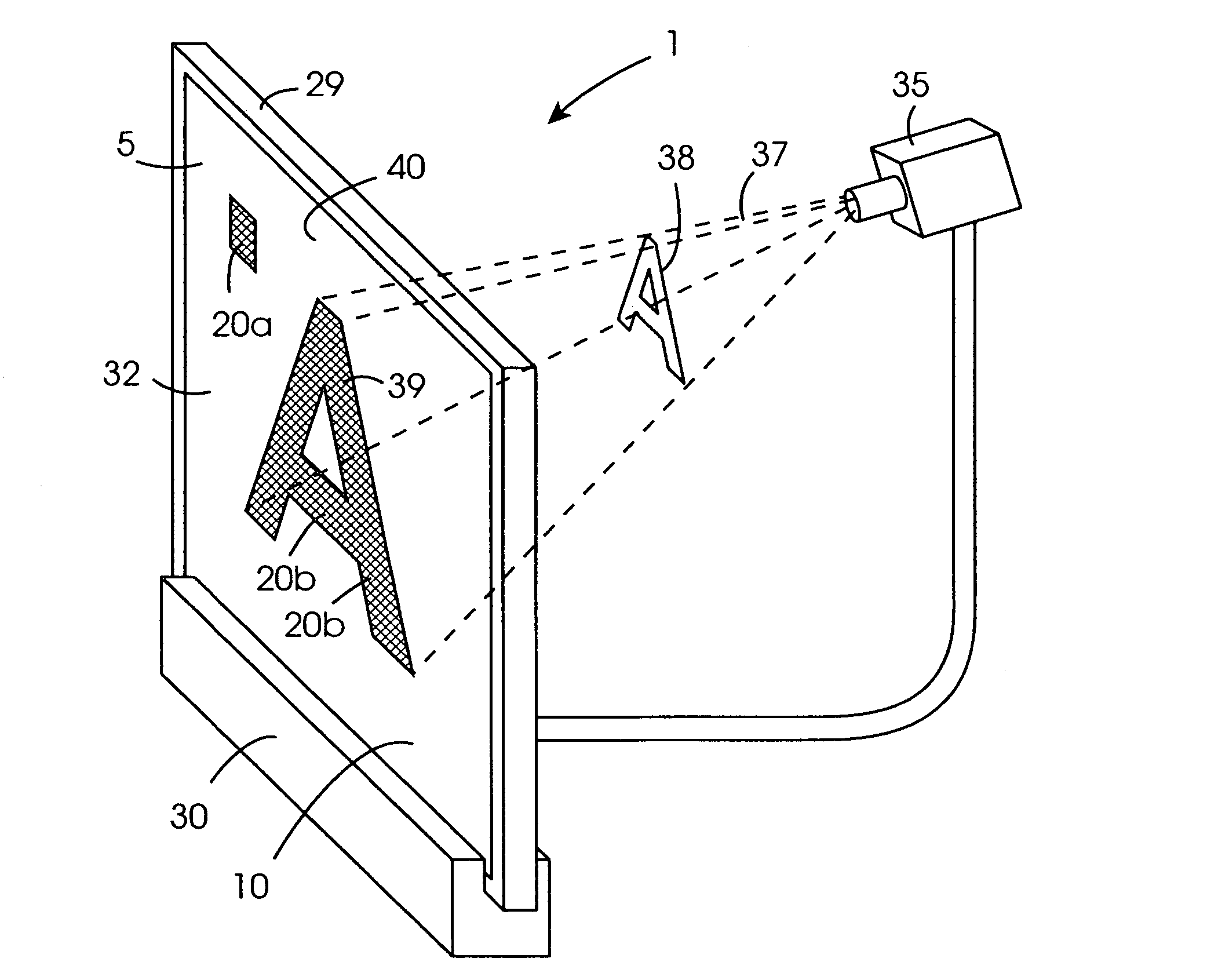
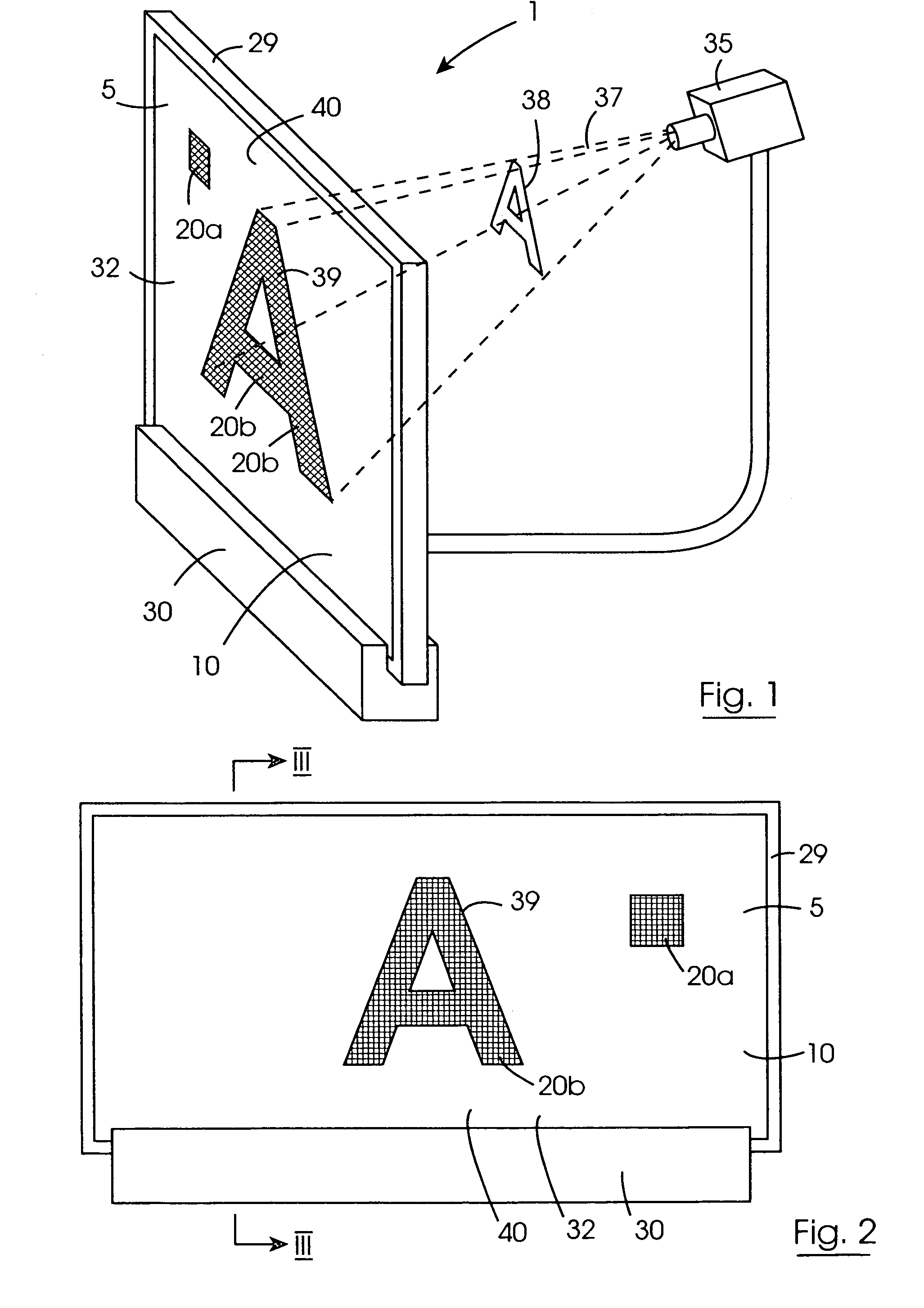
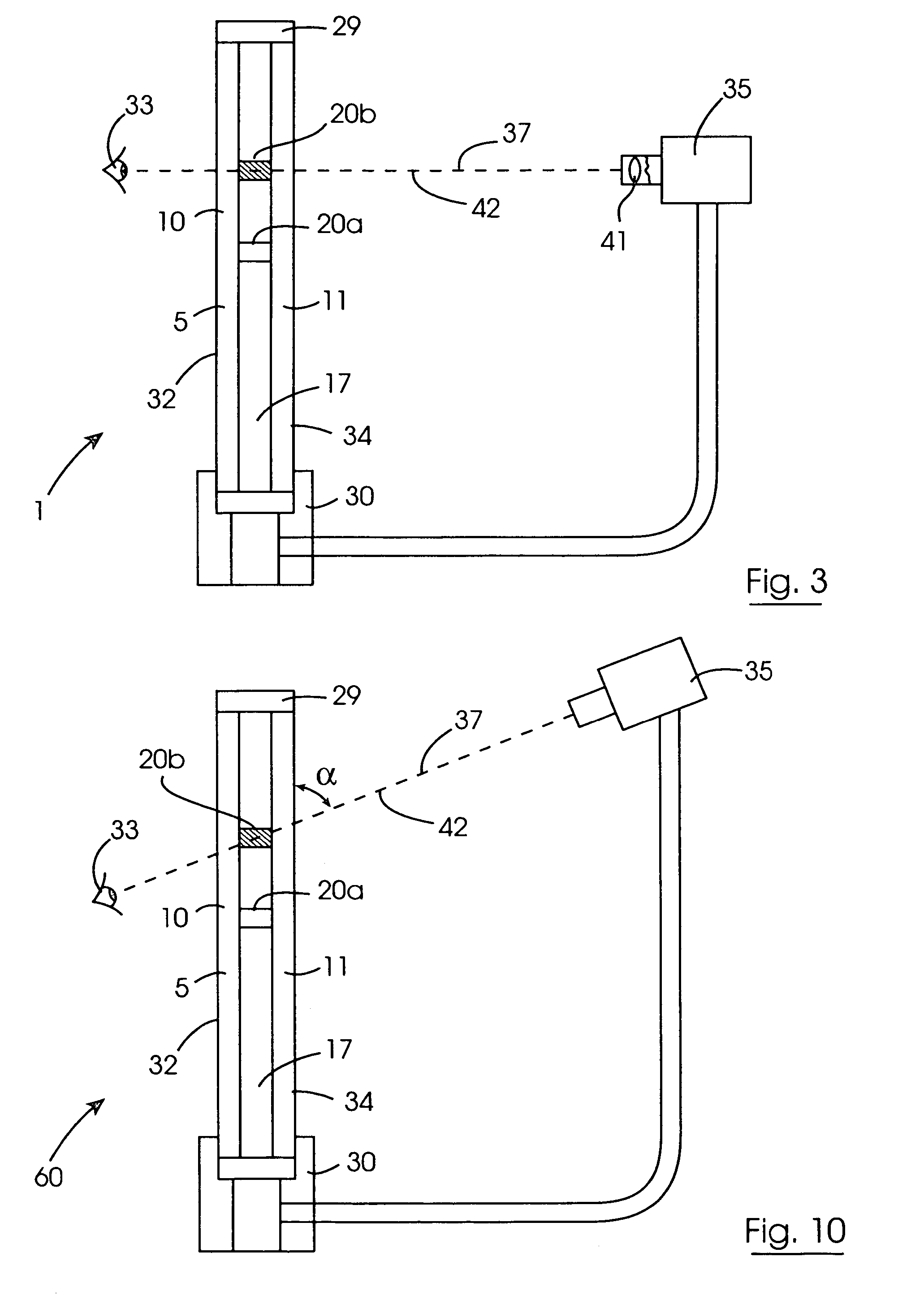
[0076]Referring to the drawings and initially to FIGS. 1 to 9 there is illustrated a visual display device according to the invention indicated generally by the reference numeral 1 for displaying a character or characters, which in this embodiment of the invention are letters, numerals and images for forming information to be displayed. The information may be static or animated, and may be data or a graphical display.

[0077]The visual display device 1 is particularly suitable for locating in a shop window 2 as illustrated in FIG. 8 for displaying data and other information, for example, price data and the like. The visual display device 1 comprises a visual display panel 5 which is suitable for mounting on or adjacent the shop window 2, and in FIG. 8 is illustrated laminated to a window pane 6 which is set in a window frame 7 of the shop window 2. Indeed, the visual display panel 5 may form all or part of the window pane 6 of a shop window, and when the visual display panel 5 forms a...


PUM

PropertyMeasurementUnit
angleaaaaaaaaaa
angleaaaaaaaaaa
angleaaaaaaaaaa

Abstract

A visual display device (1) comprises a visual display panel (5) which comprises an electro-optical medium (17) provided by a cholesteric liquid crystal medium which defines a plurality of pixels (20) which are alternately and selectively operable in a first light transmitting mode for forming a background (40) and a second light scattering mode for forming a character (39) against the background (40). A video projector (35) projects a light beam (37) at a rear major face (34) of the visual display panel (5) which defines an image (38) of a character (39) being displayed on the visual display panel (5). The light in the light beam (37) is incident on the pixels (20) which are operating in the second light scattering mode for forming the character (39) thereby increasing the brightness of the pixels (20) operating in the light scattering mode when viewed by a subject (33), and thus enhancing the contrast between the pixels (20) operating in the second light scattering mode which form the character (39), and the remaining pixels (20) which form a background (40) of the visual display panel (5).

Description

[0001]This is a National Stage entry of PCT Application No. PCT / IE02 / 00124 filed Aug. 27, 2002; the disclosure of which is incorporated herein by reference.BACKGROUND OF THE INVENTION[0002]The present invention relates to a method for operating a visual display panel, and in particular, for operating a visual display panel for displaying a character. The invention also relates to a visual display device for displaying one or more characters. Further the invention relates to a shop window comprising the visual display device.[0003]Visual display devices for displaying characters, for example, letters, numerals and the like for presenting information are well known. Such visual display devices typically comprise a visual display panel which is formed by an electro-optical medium sandwiched between a pair of transparent substrates. Typically, one of the substrates carries a plurality of row electrodes, while the other substrate carries a plurality of column electrodes. The row and colu...

Claims


Application Information

Patent Timeline
Patent Type & Authority Patents(United States)
IPC IPC(8): G06K7/14G02F1/13G02F1/13357G03B21/00G09F9/00G09F9/46G09G3/00G09G3/20G09G3/34G09G3/36
CPCG09G3/002G09G3/3406G09G2320/02
Inventor O'KEEFFE, DONALO'HALLORAN, ALBERT
Owner VLYTE INNOVATIONS LTD
Learn More