Antenna unit having a wide band

a wide band, antenna technology, applied in the direction of resonant antennas, elongated active elements, protection materials radiating elements, etc., can solve the problem of uwb technology in the presence or absence of carrier waves, difficult to plan for uwb including and difficult to include a lot of frequency components in the uwb, so as to achieve the effect of widening the band

Inactive Publication Date: 2006-07-25
MITSUMI ELECTRIC CO LTD +1
View PDF10 Cites 22 Cited by
  • Summary
  • Abstract
  • Description
  • Claims
  • Application Information

AI Technical Summary

Benefits of technology

[0014]It is therefore an object of the present invention to provide an antenna unit which is capable of widening the band.
[0015]It is another object of the present invention to provide an antenna unit which is capable of improving a frequency characteristic.

Problems solved by technology

A crucial difference between a conventional radio technology and the UWB technology is the presence or absence of a carrier wave.
The antenna has a resonance frequency which is determined by its length, it is difficult for the UWB including a lot of frequency components to make the antenna for UWB resonate.
Accordingly, the wider the frequency band of the electric wave to be transmitted is, the more difficult it makes a plan for the antenna for UWB.
However, the patch antennas are unsuitable for the UWB antennas because the patch antennas have no wideband.
In the manner which is described above, the conventional antenna such as a patch antenna is disadvantageous in that it is difficult to widen the band and wave distortions (wave expansion) occur.

Method used


Image

  • Antenna unit having a wide band
  • Antenna unit having a wide band
  • Antenna unit having a wide band

Examples


first embodiment

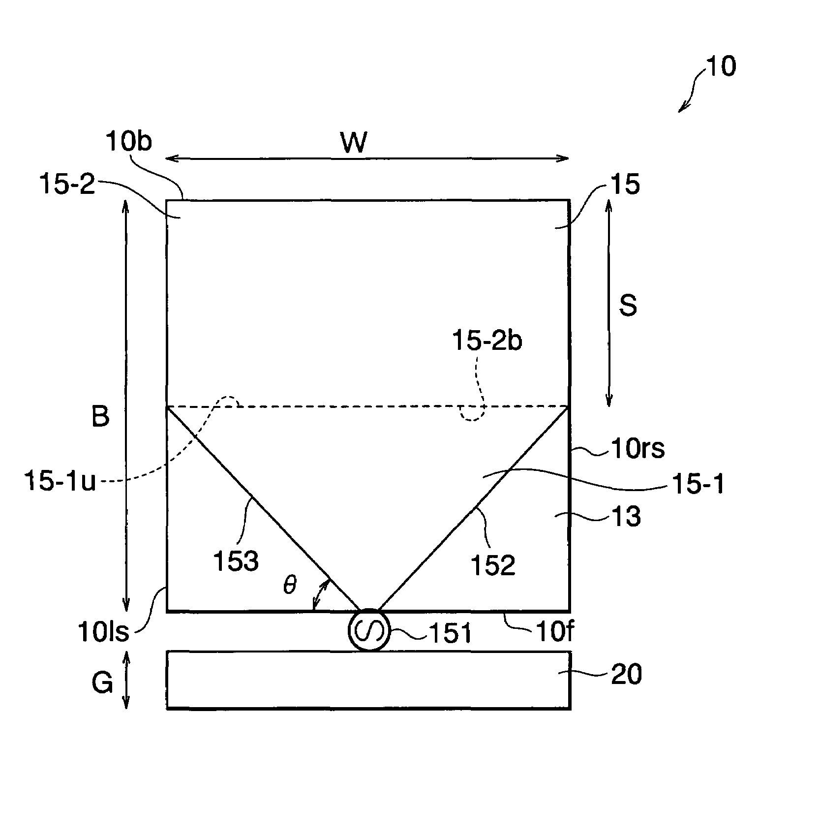
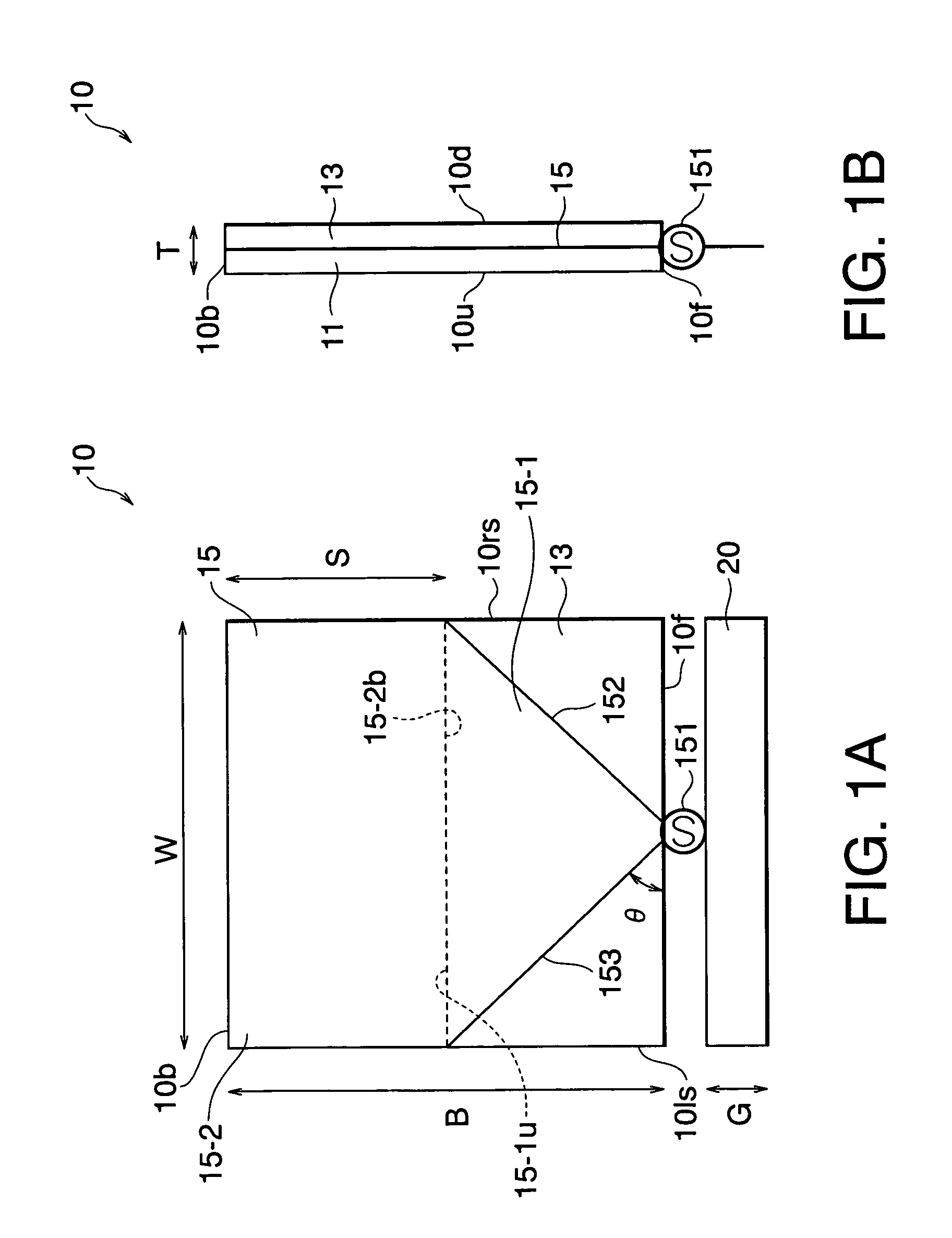
[0029]Referring to FIGS. 1A and 1B, the description will proceed to a UWB antenna 10 as an antenna unit according to the present invention. FIG. 1A is a transverse sectional plan view of the UWB antenna 10. FIG. 1B is a vertical sectional side view of the UWB antenna 10.

[0030]The UWB antenna 10 has, as whole exterior appearance, configuration of a rectangular parallelepiped (rectangular plate) having a length B, a width W, and a thickness T. In the example being illustrated, the length B is equal to 22 mm, the width W is equal to 21.6 mm, and the thickness T is equal to 0.8 mm.

[0031]The UBW antenna 10 has an upper surface 10u, a bottom surface 10d, a front surface 10f, a back surface 10b, a right-hand side surface 10rs, and a left-hand side surface 101s.

[0032]The UWB antenna 10 comprises an upper rectangular dielectric 11, a lower rectangular dielectric 13, and a conductive pattern 15 sandwiched between the upper rectangular dielectric 11 and the lower rectangular dielectric 13. Eac...

second embodiment

[0043]Referring to FIG. 3, the description will proceed to a UWB antenna 10A as an antenna unit according to the present invention. FIG. 3 is a transverse sectional plan view of the UWB antenna 10A.

[0044]The illustrated UWB antenna 10A is similar in structure to the UWB antenna 10 illustrated in FIGS. 1A and 1B except that the rectangular portion 15-2 has at least one slit 17 formed therein at the back surface 10b. In the example being illustrated in FIG. 3, the number of slits 17 is equal to three.

[0045]By forming the slits 17 in the rectangular portion 15-2, it is possible to improve a frequency characteristic of the UWB antenna 10A in the manner which will later be described.

[0046]FIG. 4 shows antenna characteristics when the number of slits 17 (cut number) of the UWB antenna 10A illustrated in FIG. 3 is changed. In FIG. 4, the abscissa represents a frequency (GHz) and the ordinate represents the reflection coefficient S11 (dB) of the S parameters.

[0047]FIG. 4 shows the antenna c...

third embodiment

[0052]Referring to FIG. 6, the description will proceed to a UWB antenna 10B as an antenna unit according to the present invention. FIG. 6 is a transverse sectional plan view of the UWB antenna 10B.

[0053]The illustrated UWB antenna 10B is similar in structure to the UWB antenna 10 illustrated in FIGS. 1A and 1B except that the UWB antenna 10B comprises a conductive pattern 15A comprising a semicircular portion 15-3 in lieu of the rectangular portion 15-2.

[0054]The semicircular portion 15-3 has an arc 15-3a and a base side 15-3b. The base side 15-3b of the semicircular portion 15-3 is in contact with the upper side 15-1u of the reversed triangular portion 15-1.

[0055]The present co-inventors confirmed that the UWB antenna 10B has an antenna characteristic which is similar to that of the UWB antenna 10 illustrated in FIGS. 1A and 1B.


PUM


Abstract

A UWB antenna has an upper dielectric, a lower dielectric, and a conductive pattern sandwiched therebetween. The conductive pattern has a feeding point at a substantially center portion of a front surface. The conductive pattern has a reversed triangular portion having a right-hand taper part and a left-side taper part which widen from the feeding point at a predetermined angle toward a right-hand side surface and a left-hand side surface, respectively, and a rectangular portion having a base side being in contact with an upper side of the reversed triangular portion. The rectangular portion may preferable have at least one slit formed therein.

Description

[0001]This application claims priority to prior Japanese patent application JP 2003-325858, the disclosure of which is incorporated herein by reference.BACKGROUND OF THE INVENTION[0002]This invention relates to an antenna unit and, more particularly, to an antenna for an ultra wideband (UWB).[0003]The UWB technology means an ultra wideband radio technology like its name and is defined as any radio technology having a spectrum that occupies a bandwidth greater than 25 percent of the center frequency, or a bandwidth of at least 1.5 GHz. In a word, the UWB technology is technology for communicating using short pulses (normally each having a pulse width of 1 ns or less) of ultra wideband so as to start a revolution in radio technology.[0004]A crucial difference between a conventional radio technology and the UWB technology is the presence or absence of a carrier wave. The conventional radio technology modulates a sinusoidal wave having a frequency called the carrier wave using various m...

Claims


Application Information

Patent Timeline
Patent Type & Authority Patents(United States)
IPC IPC(8): H01Q13/10H01Q1/38H01Q1/24H01Q1/42H01Q9/38H01Q9/40
CPCH01Q1/422H01Q1/241
Inventor MIYOSHI, AKIRANAKANO, HISAMATSU
Owner MITSUMI ELECTRIC CO LTD
Why Eureka
Try Eureka