Flexible resistive touch screen

Inactive Publication Date: 2006-07-25
EASTMAN KODAK CO
View PDF39 Cites 147 Cited by
  • Summary
  • Abstract
  • Description
  • Claims
  • Application Information

AI Technical Summary

Benefits of technology

[0010]The flexible touch screen of the present invention has the advantages that i

Problems solved by technology

This process is relatively complex and expensive and the use of an additional material such as an adhesive can be expected to diminish the clarity of the touch screen.
Such prior art spacer dots are limited in material selections to polymers that can be manufactured into small beads or UV coated from monomers.
In these prior art methods, the spacer dots may come loose and move around within the device, thereby causing unintended or inconsistent actuations.
Furthermore, contact between the conductive layers 14 and 18 is not possible where the spacer dots are located, thereby reducing

Method used


Image

  • Flexible resistive touch screen
  • Flexible resistive touch screen
  • Flexible resistive touch screen

Examples


Example

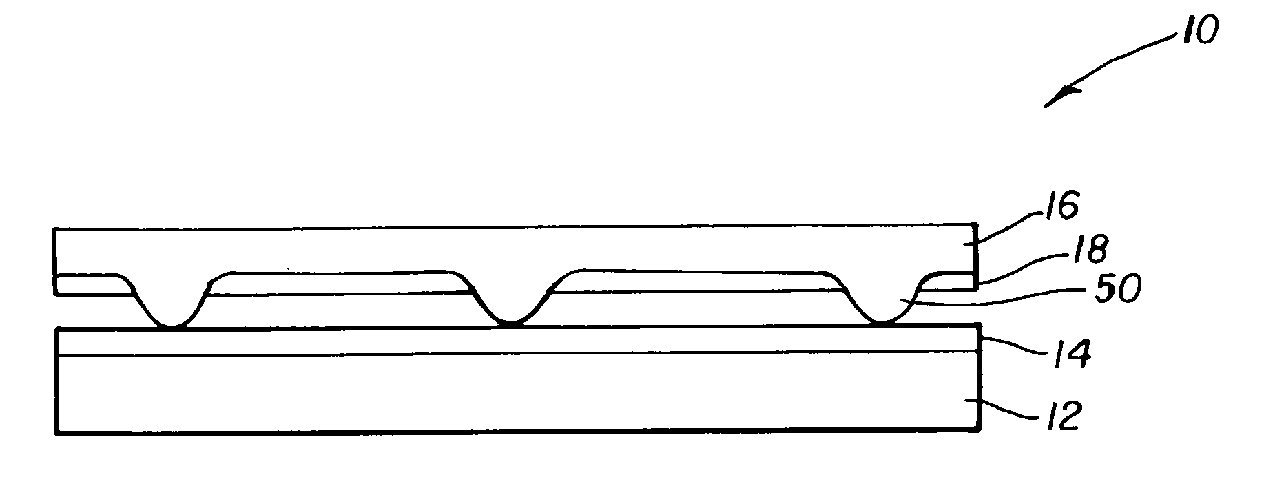
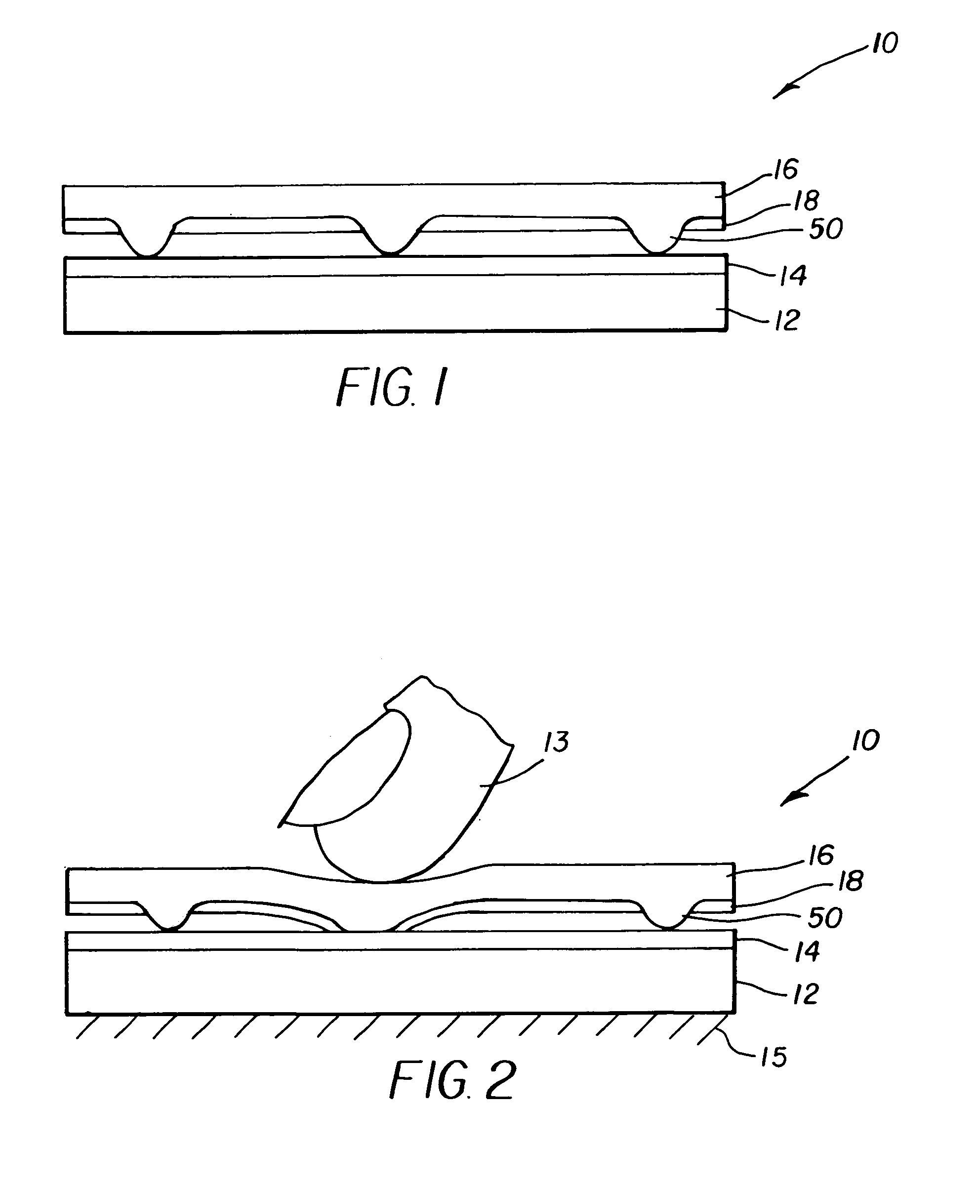
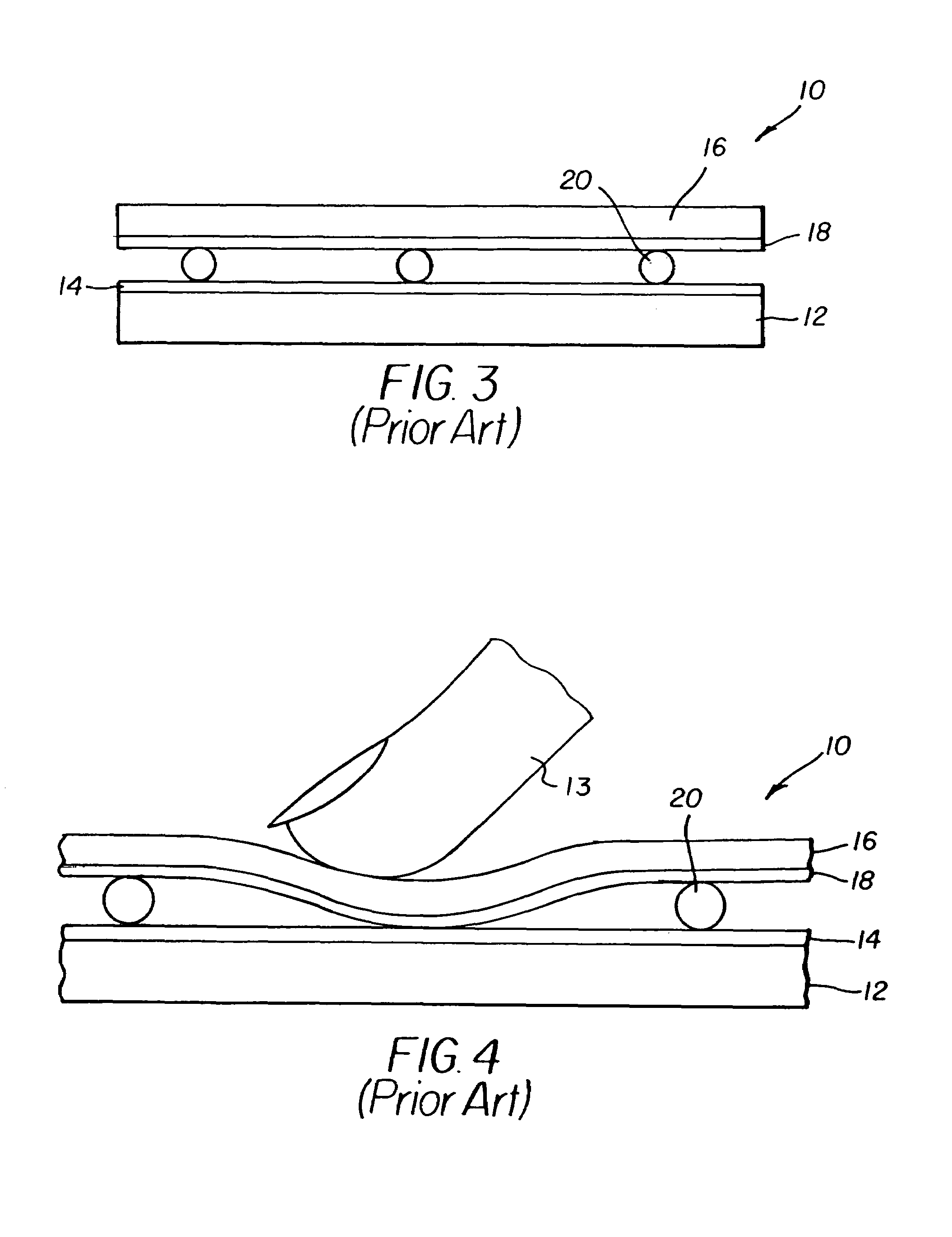
[0019]Referring to FIG. 1, the problems of the prior art resistive touch screens are overcome through the use of a transparent, flexible substrate 12 having a first conductive layer 14 located on the transparent flexible substrate 12. A flexible transparent cover sheet 16 having a second conductive layer 18 and integral compressible spacer dots 50 formed in the flexible transparent cover sheet 16 is located over the transparent flexible substrate 12. The second conductive layer 18 of the flexible transparent cover sheet 16 does not cover the peaks of the integral compressible spacer dots 50. The word “integral” means that the compressible spacer dots 50 are formed in and comprise the same material as the flexible transparent cover sheet 16 for example by molding or embossing.

[0020]Referring to FIG. 2, in operation, the flexible substrate has less flexibility than the flexible cover sheet 16, or is supported, for example by a backing surface 15. The integral compressible spacer dots ...


PUM


Abstract

A flexible, resistive touch screen includes a transparent, flexible substrate; a first conductive layer located on the flexible substrate; a flexible transparent cover sheet having integral compressible spacer dots; and a second conductive layer located on the flexible transparent cover sheet, the peaks of the integral compressible spacer dots extending through the second conductive layer, whereby, when a force is applied to the touch screen at the location of one of the compressible spacer dots, the compressible spacer dot is compressed to allow electrical contact between the first and second conductive layers.

Description

FIELD OF THE INVENTION[0001]This invention relates to flexible resistive touch screens and more particularly, to a transparent flexible cover sheet and spacer dots separating the cover sheet from a flexible substrate in a flexible resistive touch screen.BACKGROUND OF THE INVENTION[0002]Resistive touch screens are widely used in conventional CRTs and in flat-panel display devices in computers and in particular with portable computers.[0003]FIG. 3 shows a portion of a prior art resistive touch screen 10 of the type shown in Published US Patent Application No. 2002 / 0094660A1, filed by Getz et al., Sep. 17, 2001, and published Jul. 18, 2002, which includes a rigid transparent substrate 12, having a first conductive layer 14. A flexible transparent cover sheet 16 includes a second conductive layer 18 that is physically separated from the first conductive layer 14 by spacer dots 20 formed on the second conductive layer 18 by screen printing.[0004]Referring to FIG. 4, when the flexible tra...

Claims


Application Information

Patent Timeline
IPC IPC(8): G09G5/00G06F3/041G06F3/03G06F3/033G06F3/045H01H13/14H01H13/712H03K17/96H03K17/965
CPCG06F3/045B42D9/004B43K31/00
Inventor COK, RONALD S.BOURDELAIS, ROBERT P.KAMINSKY, CHERYL J.
Owner EASTMAN KODAK CO
Why Eureka
Try Eureka