Temperature detection circuit and temperature detection method

a technology of temperature detection circuit and temperature detection method, which is applied in the direction of information storage, static storage, digital storage, etc., can solve the problem that the conventional temperature detector cannot detect a small temperature change, and achieve the effect of accurately detecting the temperature change of a semiconductor devi

Active Publication Date: 2006-07-25
SAMSUNG ELECTRONICS CO LTD
View PDF2 Cites 60 Cited by
  • Summary
  • Abstract
  • Description
  • Claims
  • Application Information

AI Technical Summary

Benefits of technology

[0008]The present invention provides a temperature detection circuit and method that are capable of accurately detecting the temperature change of a semiconductor device.

Problems solved by technology

That is, the conventional temperature detector cannot detect a small change of temperature.

Method used


Image

  • Temperature detection circuit and temperature detection method
  • Temperature detection circuit and temperature detection method
  • Temperature detection circuit and temperature detection method

Examples


first embodiment

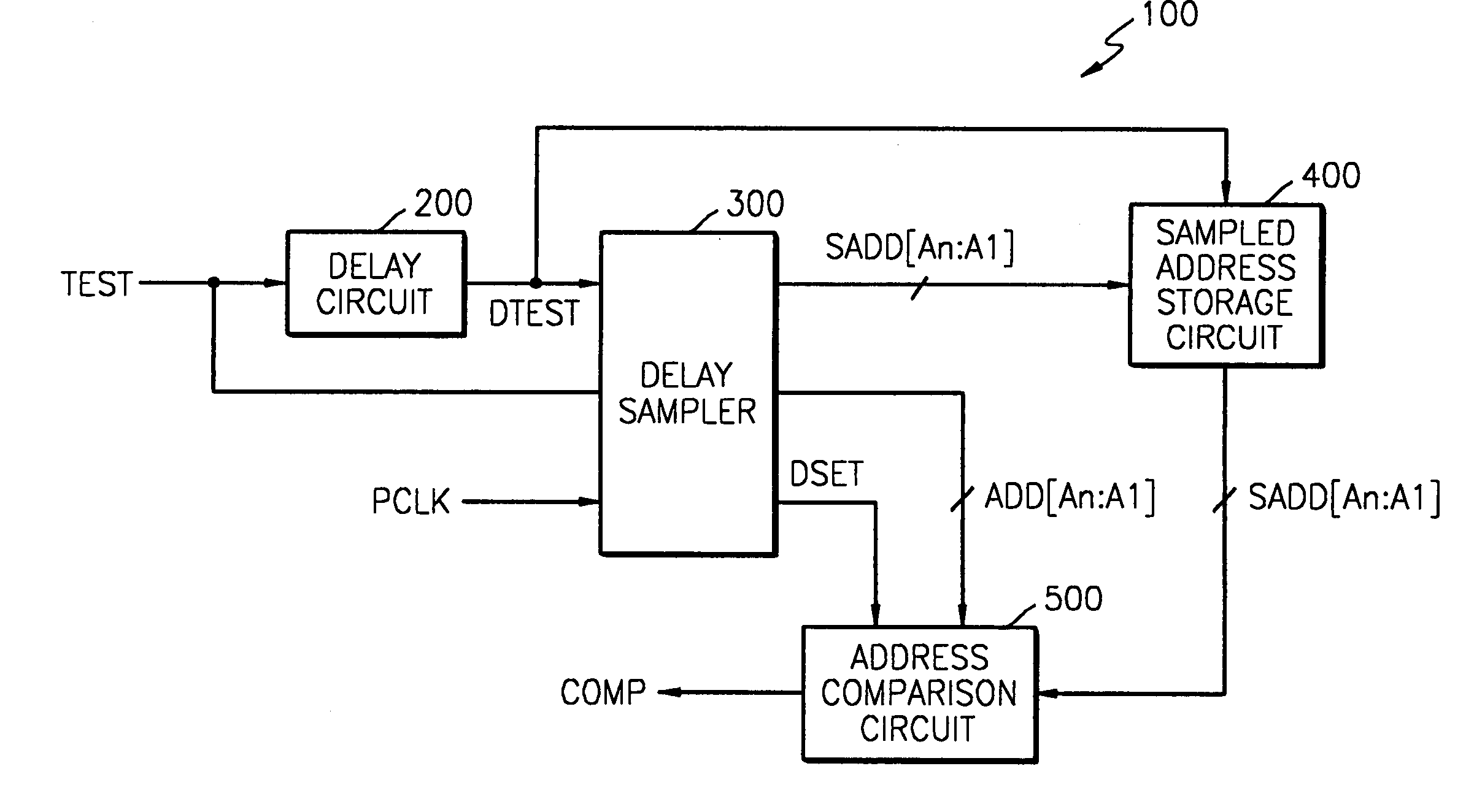
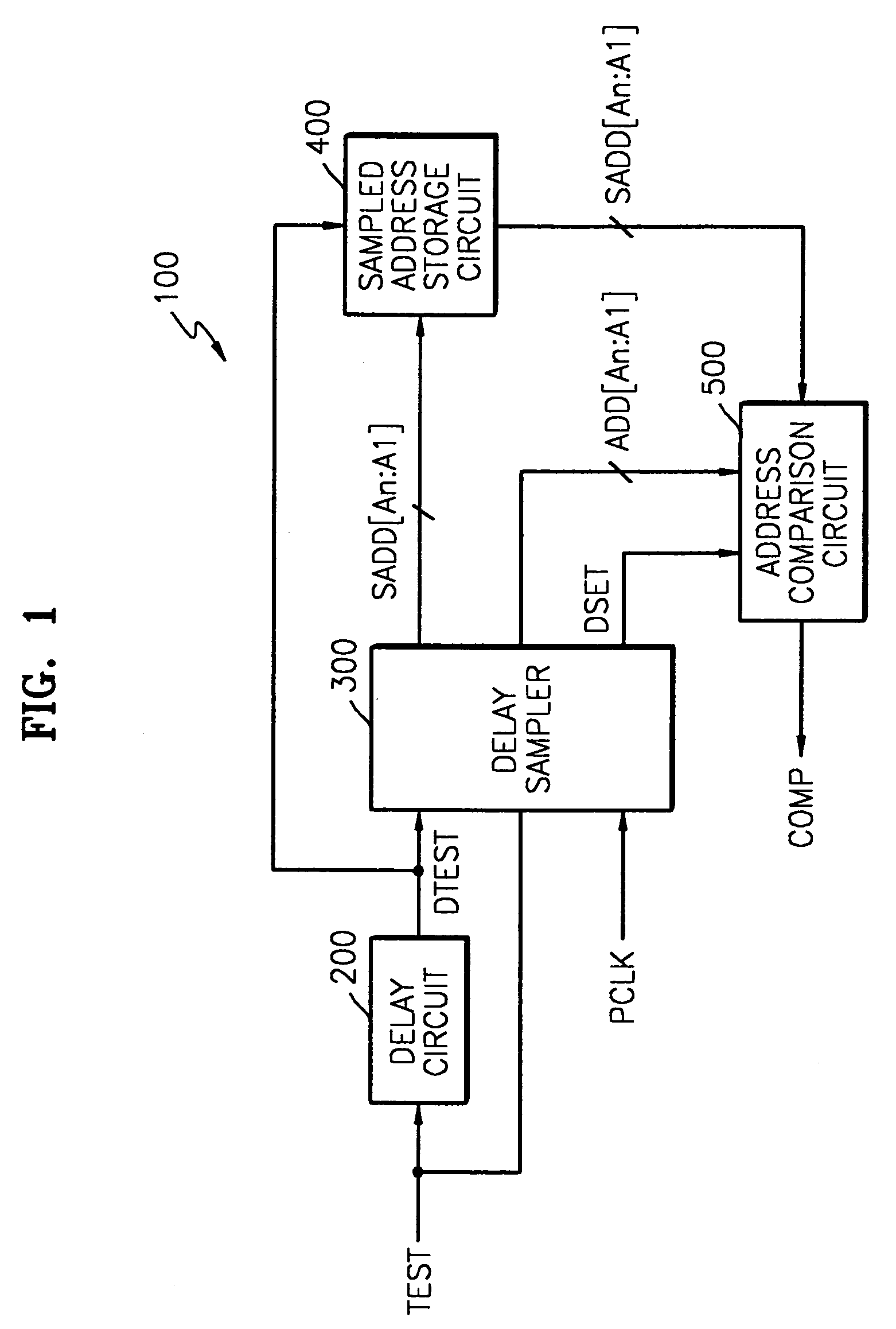
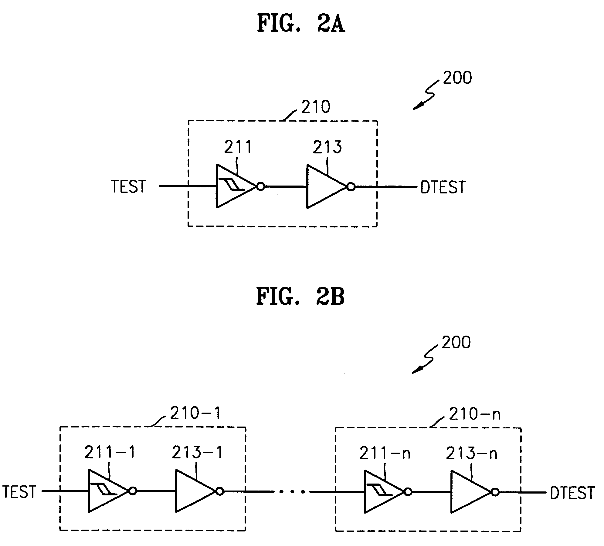
[0043]FIG. 2a shows the delay circuit of FIG. 1. Referring to FIG. 2a, the delay circuit 200 includes a delay unit 210. The delay unit 210 includes a Schmitt trigger 211 and an inverter 213.

second embodiment

[0044]FIG. 2b shows the delay circuit of FIG. 1. Referring to FIG. 2b, the delay circuit 200 includes n number of delay units 210-1 through 210-n (n is a natural number) connected in serial to each other. The respective delay units 210-1 through 210-n include Schmitt triggers 211-1 through 211-n and inverters 213-1 through 213-n, respectively.

[0045]In the case where a delay circuit 200 is implemented by n number of delay units (210-1 through 210-n) connected in serial to each other, a delay time for an input signal TEST increases and a delay amount variation according to temperature change becomes larger, as seen in FIG.9.

[0046]FIG. 3 is a circuit diagram of the delay unit of FIGS. 2a and 2b. Referring to FIG. 3, the delay unit 210 includes a Schmitt trigger 211 and an inverter 213.

[0047]The Schmitt trigger 211 has an uni-direction delay and consists of only a plurality of resistors and a plurality of transistors. The construction of the Schmitt trigger 211 is described below.

[0048]...


PUM


Abstract

A temperature detection circuit and method are provided. The temperature detection circuit samples a first delay time for an input signal at a target temperature to be detected, stores a first addresses generated as the sampled result, samples a second delay time for the input address at a present operating temperature, compares a second addresses generated as the sampled result with the first addresses, and generates a detection signal if the target temperature to be detected is the same as the present operating temperature. The temperature detection method is performed by the temperature detection circuit.

Description

BACKGROUND OF THE INVENTION[0001]This application claims the priority of Korean Patent Application No. 2003-50499, filed on Jul. 23, 2003, in the Korean Intellectual Property Office, the disclosure of which is incorporated herein in its entirety by reference.[0002]1. Field of the Invention[0003]The present invention relates to a temperature detection circuit and method, and more particularly, to a temperature detection circuit and method, which sample the delay time change of a delay circuit according to temperature change, change the sampled result to an address, and detect a temperature using the address.[0004]2. Description of the Related Art[0005]Along with the high-integration, miniaturization, and low power of semiconductor devices, various methods have been developed to reduce an amount of current consumed by the semiconductor device.[0006]A semiconductor device including DRAMs controls its self-refresh period differently according to temperature change in order to reduce cur...

Claims


Application Information

Patent Timeline
Patent Type & Authority Patents(United States)
IPC IPC(8): G11C7/04G11C7/00G11C11/406
CPCG11C5/143G11C7/04G11C11/406G11C11/40626G11C29/02G11C29/50016G11C11/40615G11C11/401G11C2029/5002
Inventor HONG, SANG-PYO
Owner SAMSUNG ELECTRONICS CO LTD
Why Eureka
Try Eureka