
Temperature control apparatus for a heater using an encoder switch and method thereof

Active Publication Date: 2006-07-25
PASECO
View PDF17 Cites 56 Cited by
  • Summary
  • Abstract
  • Description
  • Claims
  • Application Information

AI Technical Summary

Benefits of technology

[0009]It is an object of the present invention to provide to a temperature control apparatus for a heater using an encoder switch and a method thereof that can maintain a uniform indoor temperature by receiving a user's set temperature through an encoder switch as a digital signal, comparing an indoor temperature inputted in real time with the set temperature, and repeating an on / off operation of a burner according to the result of comparison.
[0010]It is another object of the present invention to provide a temperature control apparatus for a heater using an encoder switch and a method thereof that can prevent the heater from being frequently turned on / off and thus protect the heater by setting an operation condition of the heater so that the heater is turned on if the indoor temperature is lower than the set temperature by less than −2° C. and turned off if the indoor temperature is higher than the set temperature by more than 1° C.
[0012]It is still another object of the present invention to provide a temperature control apparatus for a heater using an encoder switch and a method thereof that makes it possible to accurately and promptly cope with the error in accordance with the kind of error by classifying and displaying the kind of error during the operation of the heater.

Problems solved by technology

However, since the conventional heater adopts an analog type temperature setting unit using a variable resistor, it has drawbacks in that it cannot perform an accurate temperature control due to the limitations and error (about 20%) in setting the temperature.

Method used


Image

  • Temperature control apparatus for a heater using an encoder switch and method thereof
  • Temperature control apparatus for a heater using an encoder switch and method thereof
  • Temperature control apparatus for a heater using an encoder switch and method thereof

Examples


Embodiment Construction

[0025]Reference will now be made in detail to the preferred embodiment of the present invention, examples of which are illustrated in the accompanying drawings. Wherever possible, the same reference numbers will be used throughout the drawings to refer to the same or like parts.

[0026]Hereinafter, the temperature control apparatus for a heater using an encoder switch and the method thereof according to the present invention will be explained with reference to the accompanying drawings.

[0027]The basic structure of the heater to which the present invention is applied is well known in the art, and the detailed explanation thereof will be omitted.

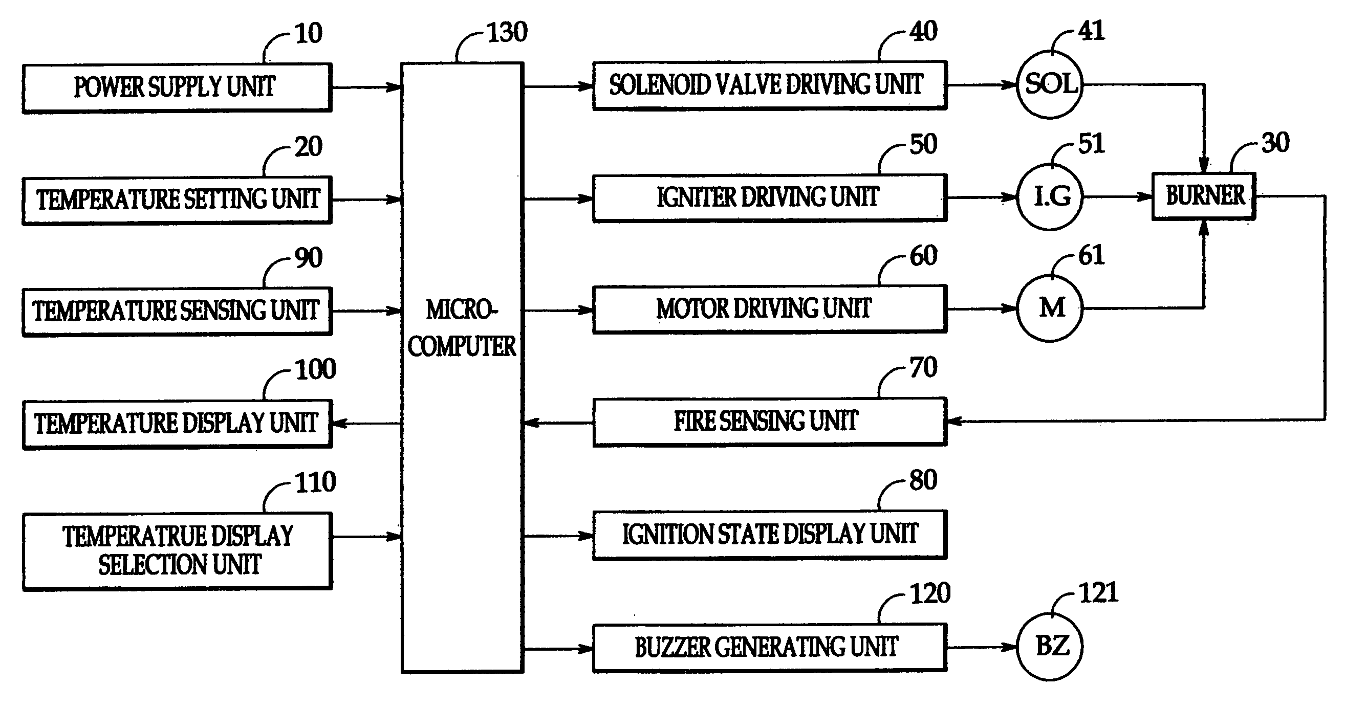
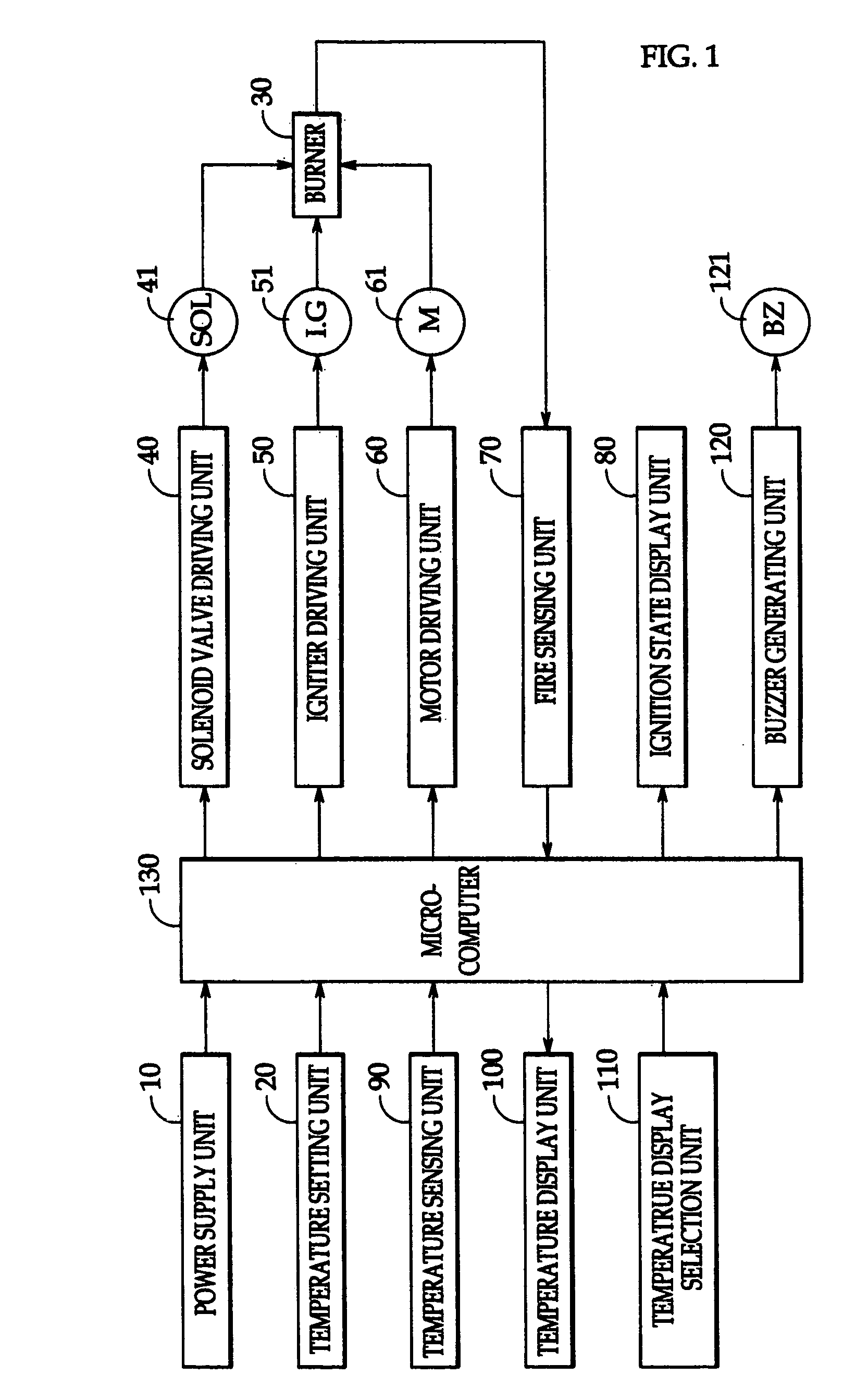
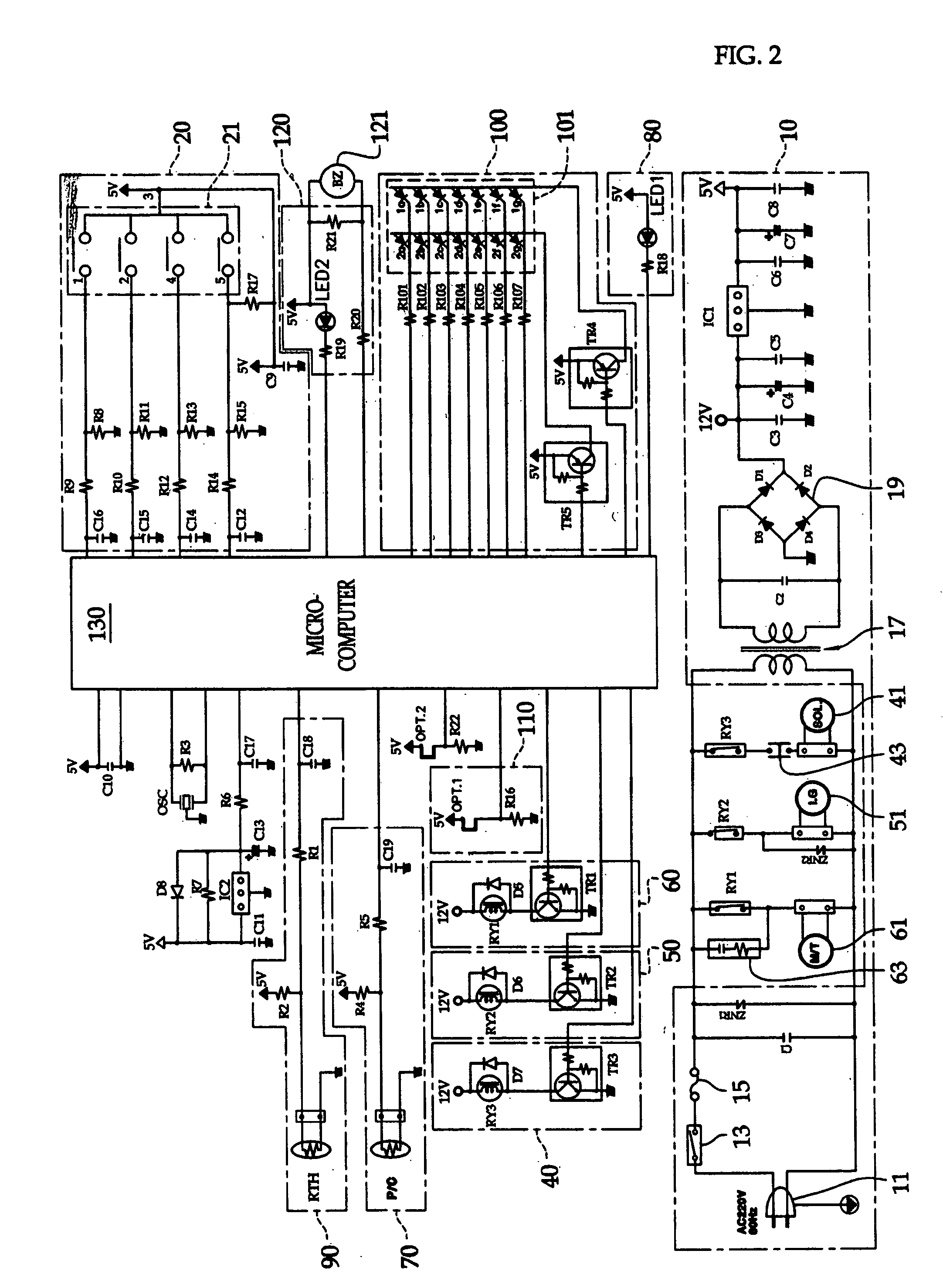
[0028]FIG. 1 is a block diagram illustrating a temperature control apparatus for a heater using an encoder switch according to an embodiment of the present invention, and FIG. 2 is a circuit diagram illustrating a temperature control apparatus for a heater using an encoder switch according to an embodiment of the present invention.

[0029]Referrin...


PUM


Abstract

Disclosed is a temperature control apparatus for a heater using an encoder switch and method thereof that controls an indoor temperature by driving a burner in accordance with a change of an indoor temperature and ventilating heated air indoors. The temperature control apparatus includes an encoder switch converting a user's set temperature value into a digital signal of a predetermined number of bits, a microcomputer for comparing the indoor temperature inputted in real time with the digital set temperature, driving the burner if the indoor temperature is lower than the set temperature by less than a predetermined temperature T1, and stopping the driving of the burner if the indoor temperature is high than the set temperature by more than a predetermined temperature T2, and a display unit for checking and displaying various kinds of error modes occurring while the burner is driven in accordance with a control signal inputted from the microcomputer.

Description

BACKGROUND OF THE INVENTION[0001]1. Field of the Invention[0002]The present invention relates to a temperature control apparatus for a heater using an encoder switch and a method thereof, and more particularly, to a temperature control apparatus for a heater using an encoder switch and a method thereof that can maintain a uniform indoor temperature by receiving a user's set temperature through an encoder switch as a digital signal, comparing an indoor temperature inputted in real time with the set temperature, and repeating an on / off operation of a burner according to the result of comparison.[0003]2. Description of the Related Art[0004]Generally, a heater can compulsorily ventilate a heat-exchanged air uniformly inside a whole room in a relatively short time, and thus it has been used for various purposes.[0005]A conventional heater operates in a manner that if a user sets a desired temperature using a temperature setting unit such as a variable resistor, it senses the indoor tempe...

Claims


Application Information

Patent Timeline
IPC IPC(8): G05D23/00G05D23/19
CPCG05D23/1917
Inventor LIM, SOO-HYUN
Owner PASECO
Learn More