Combustible sold waste pyrolysis gasification-swirl-flow combustion system

A pyrolysis gasification and combustion system technology, applied in combustion methods, combustion types, incinerators, etc., can solve problems such as land and groundwater pollution, harm to human living environment, and impact on production and life, reducing consumption, combustible solids, etc. The effect of large amount of waste pyrolysis gas and complete reaction

Pending Publication Date: 2017-09-22
江苏焱鑫科技股份有限公司
View PDF6 Cites 3 Cited by
  • Summary
  • Abstract
  • Description
  • Claims
  • Application Information

AI Technical Summary

Problems solved by technology

[0002] At present, the main treatment methods for combustible solid waste are landfill and high-temperature incineration. The problems caused by landfill are: a large amount of land is occupied, land and groundwater are polluted, and there is a strong smell near the landfill treatment site; and A large amount of dioxin and NOx produced by high-temperature incineration are discharged into the air, forming new pollutants, and causing harm to the living environment of human beings
[0003] The existing combustible solid waste treatment has the following problems: 1) Landfill is used to dispose of combustible solid waste, which causes a large amount of land to be occupied, causing land and groundwater to be polluted; 2) Landfill is used to dispose of combustible solid waste. The smell near the site is strong, which affects people's normal production and life; 3) High-temperature incineration is used to treat combustible solid waste, and a large amount of dioxin and NOx are emitted into the air, forming new pollutants and causing harm to the living environment of human beings. , 4) Regardless of whether it is landfill or high-temperature incineration to deal with combustible solid waste, the resources contained in combustible solid waste have not been recovered

Method used


Image

  • Combustible sold waste pyrolysis gasification-swirl-flow combustion system

Examples


Embodiment Construction

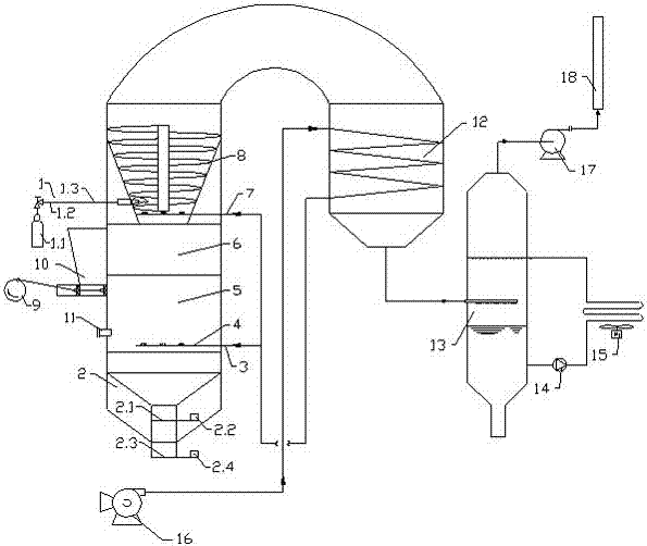
[0045] see figure 1 , the present invention relates to a combustible solid waste pyrolysis gasification-swirl combustion system, which includes a pyrolysis device, an ever-burning lamp 1, an automatic feeding device 9, a silo 10, an air preheater 12, and a flue gas quenching spray device 13. Circulating water pump 14, air cooler 15, blower 16, induced draft fan 17 and chimney 18.

[0046] The pyrolysis device includes an ash removal device 2 , an air distribution plate 4 , a heating reaction chamber 5 , a pyrolysis gasification chamber 6 and a swirl combustion chamber 8 from bottom to top.

[0047] The permanent lamp 1 is arranged on the side of the swirl combustion chamber 8, and the permanent lamp includes a propane bottle 1.1, a pressure reducing valve 1.2 and a fire detector 1.3, and the outlet of the propane bottle 1.1 is connected to the swirl combustion chamber 8, and a fire is arranged on the connecting pipeline of the two. Check 1.3, the outlet of propane bottle 1.1 ...


PUM


Abstract

The invention relates to a combustible sold waste pyrolysis gasification-swirl-flow combustion system. The combustible sold waste pyrolysis gasification-swirl-flow combustion system comprises a pyrolysis device, an air preheater, a flue gas quenching spraying device, a circulating water pump, an air cooler, an air blower and a draught fan, wherein the pyrolysis device comprises an ash removal device, an air distributing plate, a heating reaction chamber, a pyrolysis gasification chamber and a swirl-flow combustion chamber from bottom to top; one path of a hot air outlet of the air preheater is accessed into a heat supply channel in the air distributing plate, and the other path of the hot air outlet is accessed into the swirl-flow combustion chamber; an outlet of the air blower is accessed into the air preheater; a flue gas outlet of the swirl-flow combustion chamber is accessed into the air preheater; a flue gas outlet of the air preheater is accessed into a flue gas quenching spraying absorbing tower; a flue gas outlet of the flue gas quenching spraying absorbing tower is accessed into the draught fan; a circulating water outlet of the flue gas quenching spraying absorbing tower is accessed into the air cooler; and an outlet of the air cooler is accessed into the flue gas quenching spraying absorbing tower. The combustible sold waste pyrolysis gasification-swirl-flow combustion system is high in pyrolysis efficiency, is small in tail gas emission amount and is small in environmental pollution.

Description

technical field [0001] The invention relates to a combustible solid waste pyrolysis gasification-swirl flow combustion system, which is used for treating combustible solid waste. It belongs to the field of environmental protection technology. Background technique [0002] At present, the main treatment methods for combustible solid waste are landfill and high-temperature incineration. The problems caused by landfill are: a large amount of land is occupied, land and groundwater are polluted, and there is a strong smell near the landfill treatment site; and A large amount of dioxin and NOx produced by high-temperature incineration are discharged into the air, forming new pollutants, and bringing harm to the living environment of human beings. It is the demand of human development to be able to treat combustible solid waste cleanly, efficiently and with low energy consumption. At present, research on the mechanism of efficient and clean utilization of combustible solid waste i...

Claims


Application Information

Patent Timeline
Patent Type & Authority Applications(China)
IPC IPC(8): F23G5/027F23G5/04F23G5/44F23L15/00F23J1/00F23J15/06
CPCF23G5/027F23G5/04F23G5/44F23J1/00F23J15/06F23L15/00Y02E20/34
Inventor 孟庆周渊博李葳朱海航陆文杰李庆伟张翠新朱益
Owner 江苏焱鑫科技股份有限公司
Why Eureka
Try Eureka