Method and apparatus for detecting and resolving circularflow paths in graphical programming systems

a graphical programming system and circularflow technology, applied in the field of computer programming, can solve problems such as object blockag

Inactive Publication Date: 2006-07-25
NATIONAL INSTRUMENTS
View PDF24 Cites 21 Cited by
  • Summary
  • Abstract
  • Description
  • Claims
  • Application Information

AI Technical Summary

Benefits of technology

[0017]Briefly, the invention relates to a system for detecting and resolving circular paths within a graphical flow diagram that represents the logical operation of an application program. The flow diagram is preferably formed by interconnecting a plurality of symbolic representations that correspond to program objects configured to execute associated functions in response to corresponding triggering events. The functions of the program objects are selectively called upon and executed by the application program at run-time. According to the invention, a busy indicator is established at a given program object. When the given program object is triggered by its corresponding event, the object tests its busy indicator to determine whether it is already in the process of executing its associated function in response to a previous triggering event. If the given program object is not currently executing, it proceeds to execute its associated function. If, however, testing of the busy indicator signifies that the given program is already in the process of executing its associated function, the object is blocked from executing in response to this subsequent triggering event. In this manner, circular paths defined within the flow diagram are ascribed a known and determinative implementation, thereby avoiding the generation of un-intended results by the application program and the possible overwhelming of the computer's resources.

Problems solved by technology

If, however, testing of the busy indicator signifies that the given program is already in the process of executing its associated function, the object is blocked from executing in response to this subsequent triggering event.

Method used


Image

  • Method and apparatus for detecting and resolving circularflow paths in graphical programming systems
  • Method and apparatus for detecting and resolving circularflow paths in graphical programming systems
  • Method and apparatus for detecting and resolving circularflow paths in graphical programming systems

Examples


Embodiment Construction

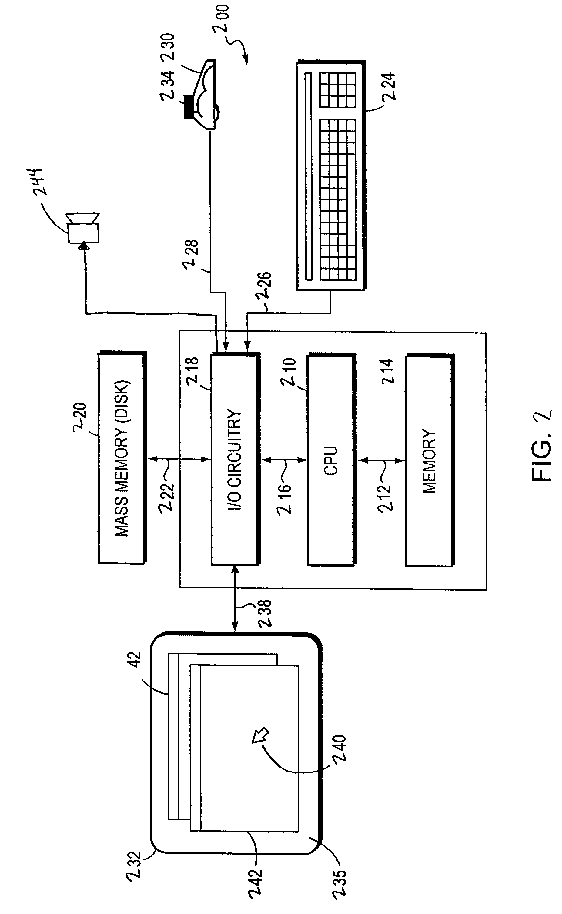
[0031]FIG. 2 illustrates a computer system 200 comprising a central processing unit (CPU) 210 coupled between a memory 214 and input / output (I / O) circuitry 218 by bi-directional buses 212 and 216, respectively. The memory 214 typically comprises random access memory (RAM) for the volatile storage of information, including application programs and an operating system, and read only memory (ROM) for persistent storage of the computer's configuration and basic operating commands. As further described herein, the application programs and the operating system interact to control the operations of the CPU 210 and the computer system 200.

[0032]The I / O circuitry 218 may be connected to a mass memory storage unit 220, such as a disk drive, via bi-directional bus 222. In the typical system 200, the memory storage unit 220 contains instructions that can be read by the CPU 210 in order to configure system 200 to provide the program-development features of the present invention. Cursor / pointer c...


PUM


Abstract

A system that detects and resolves circular paths within a graphical flow diagram that represents the logical operation of a corresponding application program. The flow diagram is formed by interconnecting symbolic representations that correspond to program objects configured to execute associated functions in response to corresponding triggering events. The functions of the program objects are called upon and executed by the application program at run-time. At the program objects, a busy indicator is established. When a program object is triggered by its respective event, the object first tests its busy indicator to determine whether it is already in the process of executing its associated function. If not, it proceeds to execute its associated function in response to an earlier triggering event. If, however, the object is already in the process of executing its associated function, then the object is blocked from re-executing in response to this new triggering event.

Description

CROSS-REFERENCE TO RELATED APPLICATIONS[0001]This application is related to the following U.S. patent applications:[0002]U.S. patent application Ser. No. 09 / 483,123 entitled, A PROGRAM-DEVELOPMENT ENVIRONMENT FOR USE IN GENERATING APPLICATION PROGRAMS, filed Jan. 14, 2000, now U.S. Pat. No. 6,701,513 which issued on Mar. 2, 2004;[0003]U.S. patent application Ser. No. 09 / 483,760 entitled METHOD AND APPARATUS FOR RESOLVING DIVERGENT PATHS IN GRAPHICAL PROGRAMMING ENVIRONMENTS, filed Jan. 14, 2000, now U.S. Pat. No. 6,425,121 which issued on Jul. 23, 2002;[0004]U.S. patent application Ser. No. 09 / 483,122 entitled, REPEATING PROGRAM OBJECT FOR USE WITH A GRAPHICAL PROGRAM-DEVELOPMENT SYSTEM, filed Jan. 14, 2000, now U.S. Pat. No. 6,425,120 which issued on Jul. 23, 2002; and[0005]U.S. patent application Ser. No. 09 / 483,124 entitled, PROGRAM OBJECT FOR USE IN GENERATING APPLICATION PROGRAMS, filed Jan. 14, 2000, now U.S. Pat. No. 6,684,385 which issued on Jan. 27, 2004.BACKGROUND OF THE I...

Claims


Application Information

Patent Timeline
Patent Type & Authority Patents(United States)
IPC IPC(8): G06F9/44
CPCG06F8/34G06F11/3664G06F11/3612G06F8/38
Inventor MORGANELLI, MICHAEL F.PHILLIPS, CHRISTOPHER J.REILLY, GERARD M.
Owner NATIONAL INSTRUMENTS
Why Eureka
Try Eureka