Butterfly valve for skylight

Active Publication Date: 2006-08-01
SOLATUBE INT INC
View PDF16 Cites 36 Cited by
  • Summary
  • Abstract
  • Description
  • Claims
  • Application Information

AI Technical Summary

Benefits of technology

[0007]Each preferred valve element may define a diameter that is larger than the height of the shroud. The shroud may be formed with a lip circumscribing an inner surface of the shroud, with the valve elements engaging the lip in the closed configuration. A universal power supply that operates at voltages at least in the range from about one hundred volts (100V) to about two hundred seventy volts (270V) can energize the motor.

Problems solved by technology

In the skylight context this means that the segment, which must not only be as wide as the diameter of the flapper but also as long as the flapper diameter to adequately house the flapper, can be excessively long, causing substantial interference during installation in an existing skylight.

Method used


Image

  • Butterfly valve for skylight
  • Butterfly valve for skylight
  • Butterfly valve for skylight

Examples


Embodiment Construction

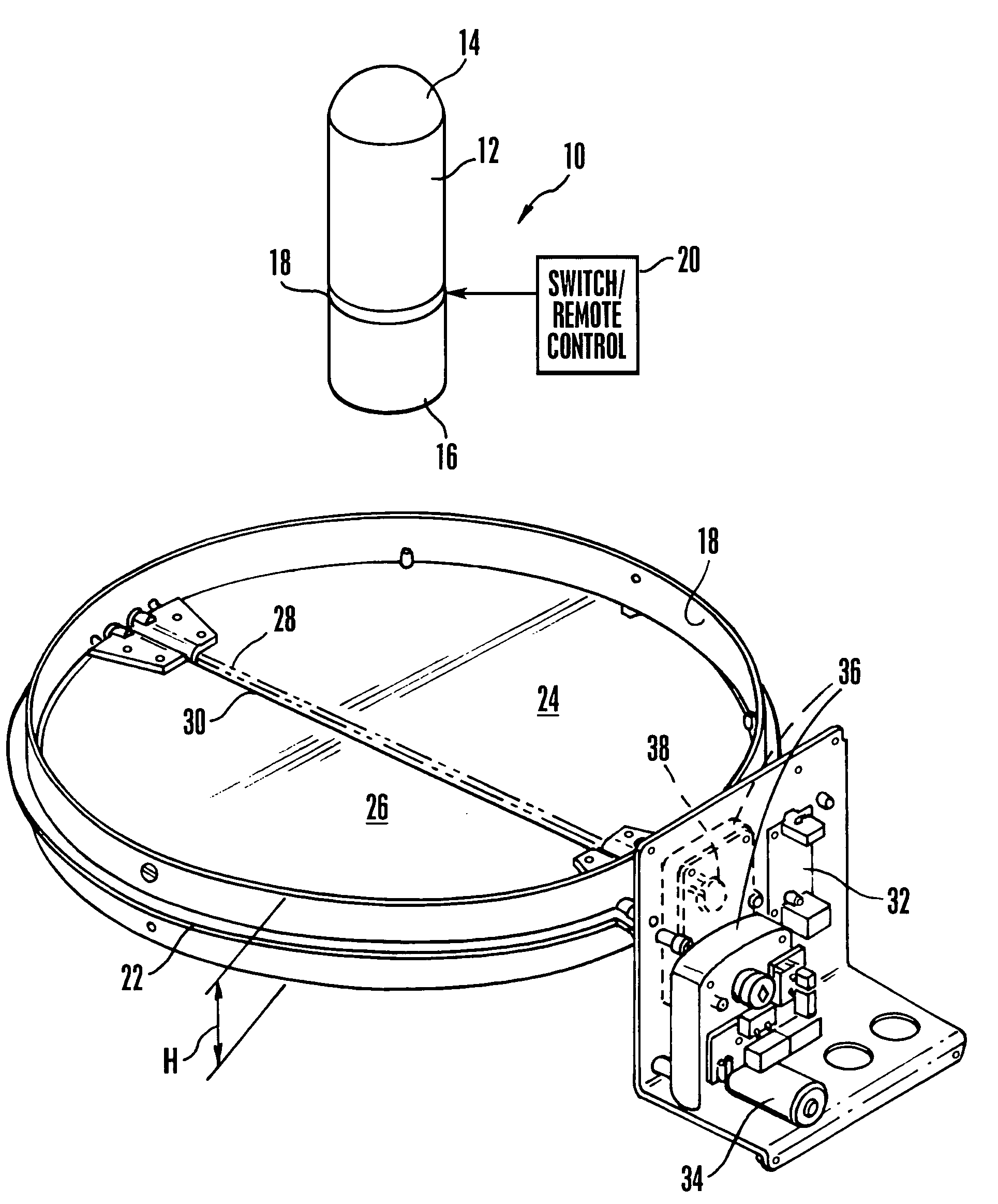
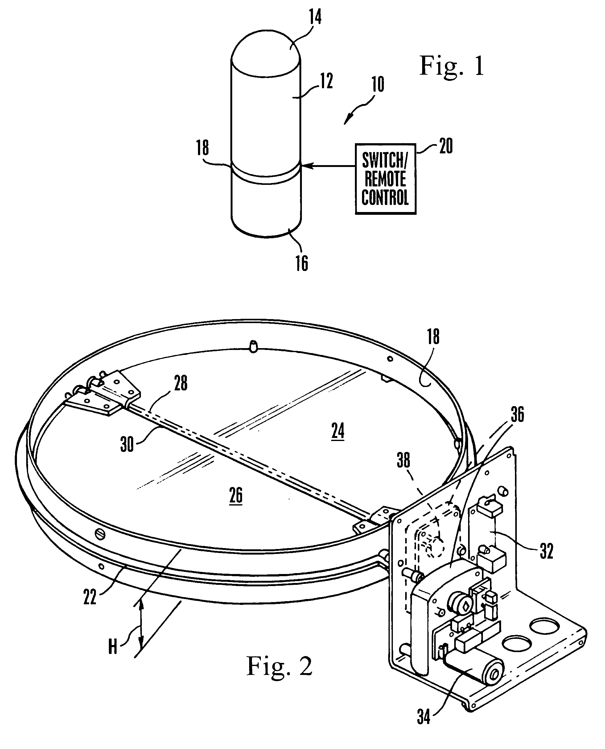
[0016]Referring initially to FIG. 1, a skylight 10 is shown that includes a light conveying structure 12 having an open upper end covered by a transparent preferably roof-mounted dome 14 and an open lower end covered by a preferably ceiling-mounted diffuser plate 16. The light conveying structure 12 may be tubular, rectangular, or other shape. As a non-limiting example, the structure shown in the present figures is tubular, it being understood that the principles set forth herein apply equally to skylights having other shapes.

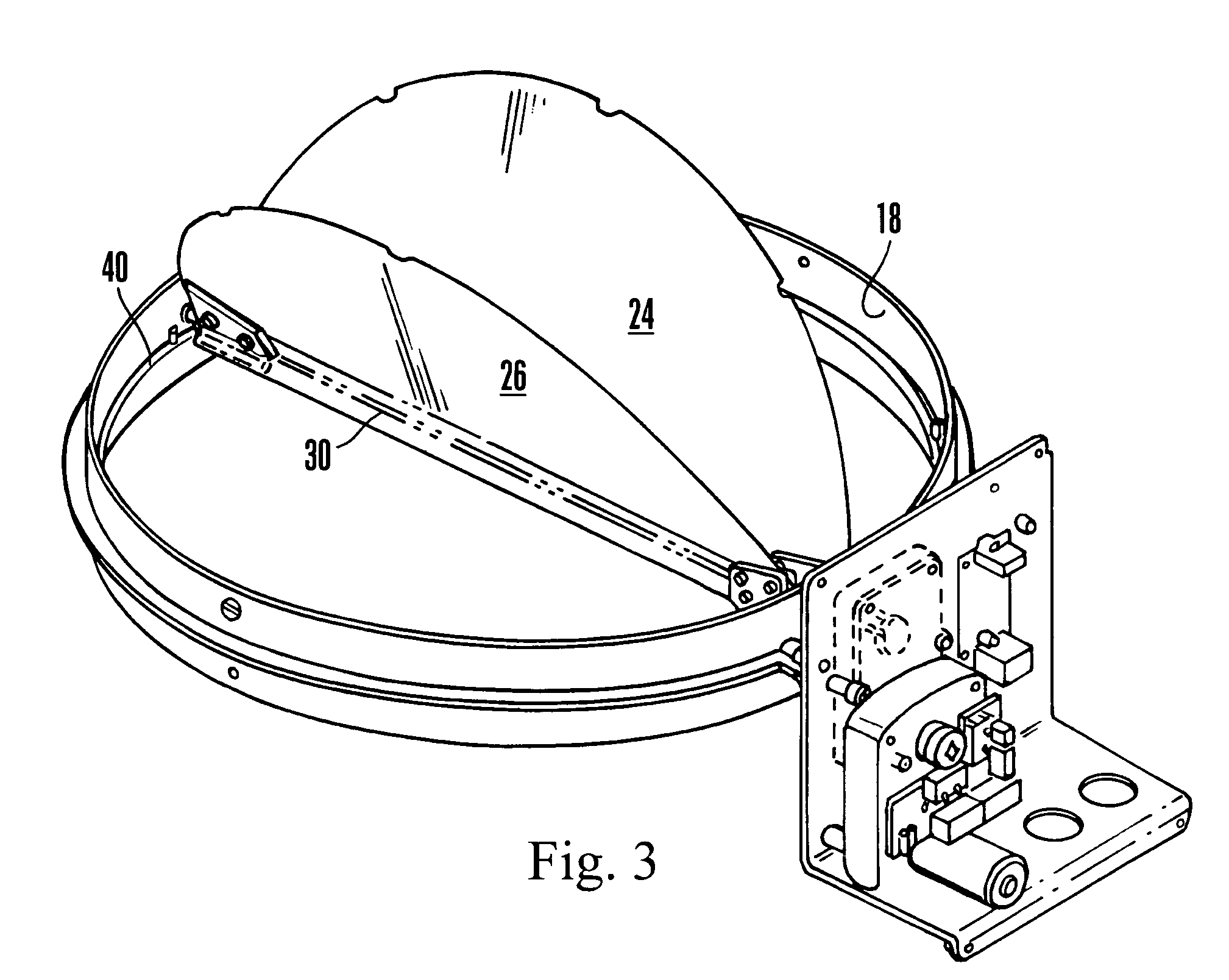
[0017]The light conveying structure 12 may include two segments as shown, with a hollow shroud 18 holding the present butterfly valve being sandwiched between the segments to selectively block light from propagating through the skylight 10. When the skylight is tubular the shroud 18 is cylindrical. As an alternative to placing the shroud 18 between the segments, it may be positioned on either end of the light conveying structure 12. When it is positioned at the...


PUM


Abstract

A valve for selectively blocking the light passageway of a skylight includes a cylindrical shroud and first and second semicircular butterfly valve elements that pivot on respective axles within the shroud to selectively block the skylight. The axles can ride on a common motor-driven cam between a horizontal orientation to block the skylight and a vertical orientation to allow light to pass. The motor can be powered by a universal power supply that can operate at anywhere from below 100 volts to above 270 volts.

Description

FIELD OF THE INVENTION[0001]The present invention relates generally to skylights.BACKGROUND OF THE INVENTION[0002]Skylights are used to illuminate buildings in a pleasing and energy-conserving way. Tubular skylights such as those made by the present assignee typically have a roof-mounted transparent cover or dome, a light conveying assembly extending down from the dome into the building to a ceiling, and a light diffuser plate covering the bottom of the assembly at the ceiling. The assembly can be tubular, or it can be rectangular or some other geometry if desired.[0003]It is sometimes desirable to stop light from being transmitted through the skylight, e.g., when a person wishes to darken a room during the day. The present invention understands that one way to do this would be to provide a disk-shaped flapper in the light conveying assembly that can be turned parallel to the assembly axis to permit light to pass, and perpendicular to the axis to block light.[0004]The present invent...

Claims


Application Information

Patent Timeline
Patent Type & Authority Patents(United States)
IPC IPC(8): E04B7/18E04D13/03
CPCE04D13/033E04D2013/034
Inventor PRENN, JOSEPH W.STEVENS, CHRISTIAN P.MUHLESTEIN, MICHAEL W.
Owner SOLATUBE INT INC
Why Eureka
Try Eureka