Hemming device and hemming method

a hemming device and a technology of a hemming device, which are applied in the direction of metal-working feeding devices, manufacturing tools, metal working apparatuses, etc., can solve the problems of uneven approach angles of pre-hemming punches b>11/b> with respect to workpiece w, unstable provisional hemming accuracy, etc., and achieve large size, large accuracy, and large size

Inactive Publication Date: 2006-08-01
NISSAN MOTOR CO LTD
View PDF16 Cites 4 Cited by
  • Summary
  • Abstract
  • Description
  • Claims
  • Application Information

AI Technical Summary

Benefits of technology

[0017]Meanwhile, the conventional hemming device stated above employs the positioning jig 9 to position the inner panel 7. Since this positioning jig 9 has a relatively long vertical stroke, the accuracy thereof deteriorates and the size is made large. Besides, it is necessary to provide a transport device dedicated to the transport of the workpiece such as a belt conveyer in addition to the positioning jig 9 so as to set the workpiece W on the hemming die 3. This makes the entire facility large in size.
[0018]It is, therefore, an object of the present invention to suppress cost increase by decreasing the number of working units, preventing each working unit from becoming large in size, and to reduce processing time by allowing the respective working units to simultaneously operate without interfering with one another even if the units are adjacent each other.
[0019]It is also an object of the present invention to improve workpiece positioning accuracy, to dispense with a transport device dedicated to the transport of a workpiece and to thereby make entire facility small in size.

Problems solved by technology

As a result, the cycle time of the working operation becomes disadvantageously longer.(2) If the shape of the workpiece W is such that the vertical position of a region to be hemmed by one working unit changes along the peripheral edge portion in FIG. 1, the approach angles of the pre-hemming punches 11 with respect to the workpiece W become uneven.
This makes provisional hemming accuracy unstable and degrades working quality.(3) It is necessary to set the direction in which the hemming punch 13 applies hemming pressure to be perpendicular to the surface of the workpiece W and to appropriately set the approach angles of the pre-hemming punch 11 with respect to the workpiece W. Due to this, it is difficult to standardize hemming punches and the hemming punches should be set in accordance with the shape of each workpiece, thereby pushing up cost.(4) To work a corner portion, a dedicated small working unit Uc is required.
This makes the entire facility large in size.

Method used


Image

  • Hemming device and hemming method
  • Hemming device and hemming method
  • Hemming device and hemming method

Examples


first embodiment

[0065]FIG. 3 is across-sectional view taken along line III—III of FIG. 4 and shows a hemming device in one embodiment according to the present invention. FIG. 4 is a plan view of the hemming device. A workpiece W to be hemmed in this hemming device is a vehicle rear door and a so-called sash door having a window frame section formed separately from a door main body. Four working units U1, U2, U3 and U4 are responsible for hemming this workpiece W. Since these four working units U1 to U4 are the same in basic constitution, description will be given herein to the working unit U1 on the left in FIG. 3.

[0066]As shown in FIG. 3, a lifter base 33 as well as a cylindrical guide bush 32 is provided vertically movably on a plurality of lifter guides 31 disposed on a base 29. A hemming die 35 which becomes a lower die, is provided on the upper surface of the lifter base 33. The workpiece W is set on this hemming die 35 in a state in which the outer panel Wo and inner panel Wi of the workpiece...

second embodiment

[0087]FIG. 14 is a cross-sectional view of a hemming device in another embodiment according to the present invention, taken along line XIV—XIV shown in FIG. 15. FIG. 15 is a plan view of the hemming device. A workpiece W to be hemmed in this hemming device is an automobile rear door or a so-called full door having a window frame portion Ww formed integrally with an outer panel Wo which become a door main body.

[0088]In this embodiment, a working unit Uw for hemming the waist portion stated above and positioned in the window frame of the full door. It is noted, however, five working units similar to the working units U1 to U4 shown in FIG. 4 for hemming the outer peripheral portion of the workpiece W are also provided.

[0089]The working unit Uw is provided on the upper end of a portion of a lifter guide 31 vertically guiding a lifter base 33, which portion protrudes upward from the lifter base 33. Here, as shown in FIG. 15, a waist hemming bracket 81 for the working unit Uw is fixed to...

third embodiment

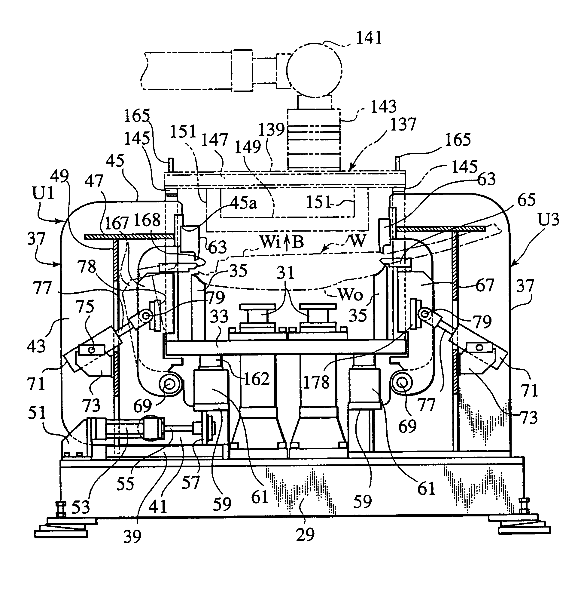
[0099]FIG. 27 is a side cross-sectional view of a hemming device in yet another embodiment according to the present invention. FIG. 28 is a plan view of the hemming device. A workpiece W to be hemmed in this hemming device is a vehicle rear door. As in the case of the first embodiment, the periphery of the workpiece W is hemmed by four working units U1, U2, U3 and U4.

[0100]As shown in FIG. 27, a lifter guide 31 disposed on a base 29 is provided with a lifter base 33 which is vertically movable. A hemming die 35 which becomes a lower die is disposed on the upper surface of the lifter base 33. The workpiece W is set onto the hemming die 35 while being positioned and gripped by a workpiece grip hand 137 in a state in which an outer panel Wo is put below an inner panel Wi and the outer panel Wo and the inner panel Wi are assembled with each other in advance.

[0101]It is noted that only the frame 139 of the workpiece grip hand 137 is shown in FIG. 27 and a mechanism, attached to this fram...


PUM

PropertyMeasurementUnit
angleaaaaaaaaaa
timeaaaaaaaaaa
shapeaaaaaaaaaa

Abstract

A hand transport section holds and transports a workplace grip hand for gripping and positioning a workpiece. The hand transport section mounts the workpiece grip hand on a hand mount so as to set the workpiece on a lower die. The hand transport section releases the workpiece grip hand and retracts. The hemming device hems the workpiece with the lower die and an upper die located above the lower die.

Description

[0001]This application is a Division of Ser. No. 09 / 805,134, filed Mar. 14, 2001, now U.S. Pat. No. 6,739,168.BACKGROUND OF THE INVENTION[0002]1. Field of the Invention[0003]The present invention relates to a hemming device and a hemming method for hemming a plate-like workpiece.[0004]2. Description of Related Art[0005]Conventionally, while the inner panel and the outer panel, for example, of a rear door which are the panel members of a vehicle are assembled with each other, hemming for hemming the peripheral edge of the outer panel and superposing the hemmed peripheral edge thereof on the peripheral edge of the inner panel is carried out by a hemming device shown in FIG. 1 which is a side view of the hemming device and in FIG. 2 which is a plan view thereof.[0006]In this hemming device, a workpiece W is positioned and set on a hemi die 3 disposed on a base 1 in a state in which the outer panel 5 is provided below an inner panel 7. The inner panel 7 is positioned and fixedly positio...

Claims


Application Information

Patent Timeline
Patent Type & Authority Patents(United States)
IPC IPC(8): B21D43/10B21D39/02
CPCB21D39/021Y10T29/53791
Inventor HARIO, HIDEHIKOMATSUMOTO, YASUYUKI
Owner NISSAN MOTOR CO LTD
Why Eureka
Try Eureka